
| Calculate Push Pull Hydraulic Cylinder Parameters | |
|---|---|
| Select Answer Mode | |
| Set Units Shortcut | |
Click save settings to reload page with unique web page address for bookmarking and sharing the current tool settings
Change the answer mode for this tool by selecting cylinder pressure, bore diameter, rod diameter, push force or pull force as the parameter to calculate instead
Related Tools
- Two linked hydraulic cylinders calculator
- Piston cylinder pressure and diameter to force calculator
- Piston cylinder force & diameter to pressure calculator
- Piston cylinder force & pressure to diameter calculator
User Guide
This tool will calculate the pressure, bore diameter, rod diameter, push force and pull force parameters for a hydraulic cylinder used to cause movement by extending and retracting a rod connected to a mechanical component.
A push pull hydraulic cylinder will include piston connected to a rod which slides into cylinder bore, and a spool valve to switch the pressure from one side of the piston to the other to control the direction of movement.
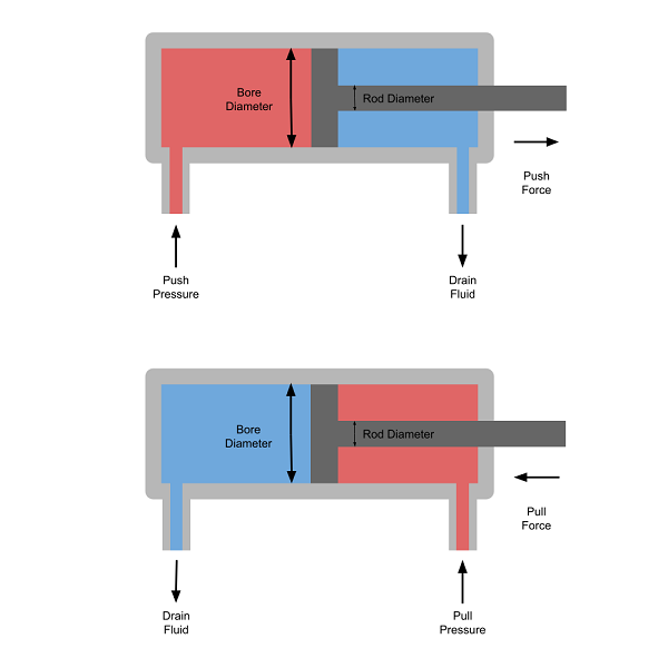
The force generated in each direction is dependent on the hydraulic pressure, and the cross-sectional area exposed to the fluid in the direction of movement.
The cross-sectional area will always be smaller on the rod side of the cylinder because the area taken up by the rod will mask part of the piston.
Formulas
The formulas used by this push pull hydraulic cylinder calculator to determine each individual parameter are as follows:
P = F / A
A = π · ø2 / 4
P = 4 · F / (π · ø2)
P = Fpush / Abore
P = Fpull / (Abore – Arod)
Abore = π · øbore2 / 4
Arod = π · ørod2 / 4
P = 4 · Fpush / (π · øbore2)
P = 4 · Fpull / π · (øbore2 – ørod2)
øbore = 2 · √ (Fpush / (P · π))
øbore = 2 · √ ((Fpull / P) + (π · ørod2 / 4)) / π)
ørod = 2 · √ ((Fpush – Fpull) / (P · π))
Fpush = P · π · øbore2 / 4
Fpull = P · π · (øbore2 – ørod2) / 4
Fpull = Fpush · (øbore2 – ørod2) / øbore2
Symbols
- P = Hydraulic pressure
- Abore = Cross sectional area of cylinder bore
- Arod = Cross sectional area of piston rod
- øbore = Diameter of cylinder bore
- ørod = Diameter of rod
- Fpull = Force on rod when retracting
- Fpush = Force on rod when extending
- π = Pi = 3.14159…
Pressure (P)
This is the hydraulic fluid pressure which is switched to either side of the piston to extend and retract the rod.
Bore Diameter (øbore)
This is the diameter of the cylinder bore. It is assumed that there is no gap between the piston and cylinder. If the effective diameter is known, which takes into account the clearance between the piston and cylinder, then this should be used instead.
Rod Diameter (ørod)
This is the diameter of the piston rod.
Push Force (Fpush)
This is the force pushing on the rod which causes it to extend.
Pull Force (Fpull)
This is the force pulling on the rod which causes it to retract.