
We have a transducer which is rated for 0-2000 psi, and it outputs 0-5 Volts. The specification document states that the accuracy is a combined LHR of +/- 0.5 %FS, how would we check this?
I am trying to create a test to check the transducer to ensure it is working properly. If I test the transducer at every 200 psi, how much allowable error can I expect to see based on the accuracy spec provided?
Featured pressure transducer products
In order to check the LHR (linearity, hysteresis, and repeatability) error of a pressure transducer, firstly the reference baseline for linearity errors needs to be chosen from one of the following three error calculation methods:
Absolute Accuracy – Straight line for a 0…2000 psi against 0 and 5 volts output device representing the best possible theoretical performance. This method is mostly used for pressure indicators and calibrators, since they are ready to use without any initial calibration adjustment.
Best Straight Line (BSL, BFSL) – Best fit straight line fit through all the calibration points. This is mathematically more complicated, because the results have to be processed to determine the best straight line. Manufacturers often use this method for millivolt output strain gauge type pressure transducers because it produces the best error for marketing purposes and indirectly shows the potential accuracy achievable if the 0 and 2000 psi reading is set to the output at the points on the virtual best straight line.
Terminal Straight Line (TSL) – Straight line drawn between the output at 0 psi and the full scale output at 2000 psi. This method cancels out any zero or span offset error which is often calibrated out when setting up the measurement instrumentation. However it tends to produce errors which are somewhere between method 1 and 2. This method is commonly used with amplified voltage and current output pressure transducers, since the installer can simply set the reading at zero and full scale pressure, and be confident that the transducer readings will be within spec.
Manufacturers do not always explain which method is used, but as mentioned above one would expect it to be TSL, but there is no guarantee, and if there is no obvious clue to which method was used, then the cautious approach is to to use the absolute accuracy method which will produce the largest errors. If it passes then you can assume it will easily pass using either of the other two methods.
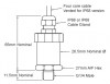
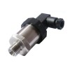
Featured pressure transducer products
 -5 to +5 psig bidirectional low range 0-5 volts output pressure sensor
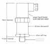 250 bar gauge range 0 to 5 volts output ceramic diaphragm pressure sensor
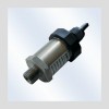 Automotive brake system 2500 psig range 0-5Vdc output synthetic hydraulic oil pressure sensor
- 3 MPa absolute range 0-5Vdc output nitrogen gas pressure sensor for aerospace testing use
You can use this tool to calculate the theoretical perfect output for each calibration point to determine the baseline when comparing with the actual readings: 0…2000 psi to 0…5Vdc output calculator.
The fail error of 0.5% FS would be equivalent to 10 psi or 0.025 V at each calibration point.
To ensure you are checking each component of the L. H. R. we would suggest:
Linearity (L) – Check increasing 200 psi increments up to 2000 psi, it is important that each calibration point is taken in one direction.
Hysteresis (H) – Check decreasing 200 psi increments from 2000 psi back down to 0 psi, it is important that these readings are taken following the previous step without releasing the pressure at 2000 psi between the two steps.
Repeatability (R) – Repeat the previous 2 steps for linearity and hysteresis
These are the suggested psi calibration points in order of testing:
- 0, 200, 400, 600, 800, 1000, 1200, 1400, 1600, 1800, 2000
- 2000, 1800, 1600, 1400, 1200, 1000, 800, 600, 400, 200, 0
- Repeat x 2
Featured pressure transducer products
 1 bar absolute pressure transducer with 0-5Vdc for freshwater
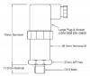 MEK solvent compatible pressure transducer with 5 bar g range and 0-5 volt output
 Standby generator 20inH2Og range 0-5Vdc output natural gas and propane pressure sensor
- 250 bar gauge range 0 to 5 volts output ceramic diaphragm pressure sensor
Related Help Guides
- Determining calibration error of Bourdon tube pressure gauge
- Pressure Sensor Accuracy Specifications
- Measurement Accuracy
- What is the difference between zero offset and zero drift?
- Choosing calibrator for pressure transmitters
- Selecting the correct pressure sensor range for low-level applications
Related Product and Application Guides

Related Technical Terms
- Accuracy
- BSL – Best Straight Line
- Compensated Temperature Range
- Digital Compensation
- g Effect
- Hysteresis
- LHR – Linearity, Hysteresis and Repeatability
- Long Term Stability/Drift
- NL – Non-Linearity
- PPM – Parts Per Million
- Precision
- Pressure Hysteresis
- Repeatability
- RTE – Referred Temperature Error
- Secondary Pressure Standard
- TEB – Temperature Error Band
- TEB – Total Error Band
- Temperature Compensation
- Temperature Error
- Thermal Hysteresis
- Threshold
- TSL – Terminal Straight Line
- TSS – Thermal Span or Sensitivity Shift
- TZS – Thermal Zero Shift
Related Online Tools
- Pressure Sensor Calculator
- Temperature Sensor Calculator
- Pressure Sensing Errors Calculator
- Pressure Measurement Accuracy and Error Calculator
Contact us about this Checking the LHR error of a 0-5 Vdc output pressure transducer page to request more information, or to discuss your application requirements.