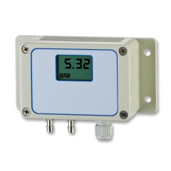
 Low range pressure sensors are characteristically very sensitive instruments, and there a few factors that need to be considered prior to, and during installation. They may look as robust as any other pressure sensor on the outside housed in a high IP rated stainless steel case, but inside there is a very thin diaphragm which is highly sensitive to acceleration and mechanical stress.
There a number of technologies out there for sensing low range pressures such as variable capacitance, variable inductance and strain gauge, but what they all have in common is a reliance on a diaphragm to collect the force and convert it to an electrical signal of some kind. In order to measure small pressure changes the diaphragm has to have a low thickness to surface area ratio in order to provide enough flexibility and thus electrical signal to be measured.
Shock and Vibration
The thinner diaphragms of lower range pressure sensors are more vulnerable to shock and vibration which can cause large zero shifts in the electrical signal. In extreme cases the diaphragm maybe destroyed by a sudden shock. On the whole though the majority of sensors are robust enough for most applications and it is mainly the effects on accuracy performance that need to be considered.
Gravity (G) Effect
One acceleration effect which is present in every installation is the acceleration due to gravity. If you consider a thin and large diameter diaphragm orientated in a horizontal plane, it will sag slightly downwards due to the effects of gravity acting on its own weight. If you now flip the diaphragm over, the opposite side will now sag and if you happen to be monitoring the output signal you would have noticed a positive and negative change in the zero pressure output due to what is called the ‘g’ effect. So unless the low pressure sensor happens to be in a zero g environment, care should be taken to install a low pressure sensor in the same orientation it was calibrated. If this is not possible, adjustments should be made to the sensor or associated measurement instrumentation to null the zero offset once installed.
Mechanical Stress Sensitivity
External mechanical stress can be picked up by a low pressure sensing diaphragm if it is closely coupled with the surrounding components that make up the rest of the pressure sensor’s construction. For example if the diaphragm is located close to a pressure connector, there maybe some coupling of material stresses when tightening during installation which will manifest as a zero offset in the output signal. Choosing a pressure sensor where the sensing diaphragm is isolated from the pressure connector ports, such as via some internal flexible tubing, will ensure that none of the stresses applied during fitting will cause a calibration shift.
Temperature Sensitivity
Most pressure sensing devices include thermal compensation circuitry to take out a large portion of the errors caused by thermal expansion of the sensing element components. For low pressure sensors these temperature effects are exaggerated due to the high sensitivity of the diaphragm to any form of induced mechanical stress. Ideally low pressure sensors should be positioned where the temperature is most constant and closest to room temperature. If this is not possible a short length of dead ended pipe should be fitted to provide a ‘stand off’ for the sensor, so that the media inside the pipe cools to ambient temperature before reaching the sensor.
