
I am looking to convert an AC signal from 0 to 50 volts into DC signal of 0 to 10 volts?
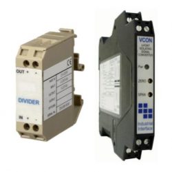
We would suggest using the VCON-AC, however the VON-AC is limited to 30Vac max, therefore in order to use it with 0-50 volts ac input signal, it will need to be reduced using another module, the DIVIDER, which can be configured to reduce an AC signal by a set ratio.
The VCON-AC and DIVIDER can be factory configured and calibrated together. The installer can then join them together by wiring the output of the DIVIDER with the input of the VCON-AC when mounting them on a DIN rail.
VCON-AC Voltage Input Signal Converter
- VCON-AC data sheet
- SKU ID: s1-vconac-0001
- Input Type: 0-50Vac using a II-Divider unit
- Output Type: 0-10Vdc
- Supply: 12, 24 Vdc or 24Vac
- Isolation: Full 3-Port
- Installation: DIN Rail TS35
- Electrical Connections: Screw clamp with pressure plate
- Accessories: II-DIVIDER-002 voltage divider unit
Converting mid-range AC voltages for DC process control systems
In industrial monitoring and control environments, it is frequently necessary to interface alternating current signals with DC-based logic controllers or data acquisition systems. This application story details a solution for accurately converting a 0-50Vac signal into a proportional 0-10Vdc output, ensuring compatibility with standard industrial instrumentation while maintaining electrical safety and signal integrity.
- Application: Monitoring AC voltage levels that exceed the standard direct input threshold of signal converters.
- Challenge: Safeguarding sensitive DC electronics from higher AC potentials while maintaining high linearity and accuracy.
- Solution: A dual-stage approach utilizing a passive voltage divider coupled with a 3-port isolated signal converter.
- Outcome: A safe, DIN rail-mounted solution providing a precise 0-10Vdc analog representation of a 0-50Vac source.
An engineering requirement arose for a method to monitor an AC voltage source ranging from 0 to 50Vac and translate it into a linear 0-10Vdc signal suitable for an analog input card on a programmable logic controller. While many standard signal conditioners can accept low-level AC signals, a 50Vac input exceeds the maximum direct-entry threshold of many high-accuracy converters. To address this, the solution involves the integration of a voltage divider module working in series with a signal conversion unit. The first stage of the process utilizes a passive divider unit, which is specifically designed to reduce higher AC or DC voltages down to safer, manageable levels. By applying a fixed reduction ratio, the 50Vac signal is attenuated to a level that falls within the optimal operating window of the primary converter, ensuring the downstream electronics are protected from over-voltage conditions and potential thermal damage.
The secondary stage of the solution features the VCON-AC series, an isolating signal converter configured to receive the attenuated output from the divider. This unit performs the critical task of converting the RMS AC value into a high-level DC voltage. One of the primary technical advantages of the VCON-AC series is its full 3-port isolation. This feature provides galvanic separation between the input signal, the output signal, and the power supply, effectively eliminating ground loops and protecting the control system from transient surges or common-mode noise. This is particularly vital in industrial settings where electrical interference can degrade signal accuracy. The unit is factory-calibrated alongside the divider to ensure the cumulative error of the two components is minimized, providing a high degree of linearity across the entire 0-50V range.
For the installation engineer or instrument technician, the combination of these two modules offers a compact and robust solution for TS35 DIN rail mounting. The VCON-AC series is housed in a slim 17.5mm wide enclosure, making it ideal for high-density control panels where space is a premium. The units feature screw clamp terminals with pressure plates, ensuring secure and reliable electrical connections even in environments prone to vibration. Furthermore, the flexible power supply options allow the system to operate from 12Vdc, 24Vdc, or 24Vac sources, providing significant versatility across different site infrastructures. By utilizing the VCON-AC series in conjunction with the divider, users benefit from a pre-configured, “plug-and-play” measurement chain that simplifies commissioning and ensures long-term stability in process monitoring applications.
Step-by-Step calibration procedure for this dual-module setup
This technical calibration procedure outlines the steps required to verify and adjust the accuracy of a measurement chain consisting of a DIVIDER series module and a VCON-AC series isolating signal converter, specifically configured for a 0-50Vac input and a 0-10Vdc output. This process is intended for instrument technicians or calibration engineers to ensure the system maintains high linearity and precise signal translation within an industrial control environment.
Equipment Requirements
- A calibrated AC voltage source (RMS) capable of providing a stable 0 to 50Vac signal.
- A high-precision digital multimeter (DMM) set to measure DC voltage (0-10V range).
- A 24Vdc or 24Vac power supply (depending on the specific VCON-AC model requirements).
- A small insulated terminal screwdriver for adjusting the multi-turn potentiometers.
Setup and Connections
- Mounting: Ensure both the DIVIDER and the VCON-AC are securely mounted on a TS35 DIN rail.
- Primary Input: Connect the 0-50Vac signal source to the input terminals of the DIVIDER unit.
- Inter-module Wiring: Connect the output terminals of the DIVIDER to the process input terminals of the VCON-AC (typically terminals 4 and 5).
- Output Monitoring: Connect the DMM to the VCON-AC output terminals (typically terminals 10 and 12), ensuring correct polarity for the 0-10Vdc signal.
- Power: Apply the appropriate supply voltage to the VCON-AC power terminals (typically 1 and 2). Allow a warm-up period of at least 15 minutes to ensure thermal stability of the internal components and the galvanic isolation circuitry.
Calibration Procedure
1. Zero Point Adjustment
Set the AC voltage source to 0.00Vac (or the designated minimum of the range). Observe the reading on the DMM. Locate the “Zero” potentiometer on the front panel of the VCON-AC. Carefully adjust the Zero pot until the DMM displays exactly 0.000Vdc. If the application requires a live zero (e.g., 2-10Vdc), adjust until the specific offset value is reached.
2. Full-Scale (Span) Adjustment
Increase the AC voltage source to the maximum input value of 50.00Vac RMS. Observe the output on the DMM. Locate the “Span” potentiometer on the VCON-AC front panel. Adjust the Span pot until the DMM displays exactly 10.000Vdc.
3. Linearity Verification
To ensure the signal converter is operating linearly across the entire 50Vac span, check the output at several intermediate points. For a 0-50V to 0-10V configuration, the following verification points are recommended:
- Apply 12.50Vac: Output should be 2.500Vdc.
- Apply 25.00Vac: Output should be 5.000Vdc.
- Apply 37.50Vac: Output should be 7.500Vdc.
4. Iterative Fine-Tuning
Because the Zero and Span adjustments can occasionally be interactive in high-precision analog circuits, it is best practice to repeat steps 1 and 2. Re-apply 0Vac to check the zero, then re-apply 50Vac to check the span. Adjust as necessary until both points are accurate without further intervention.
Technical Notes
- Isolation Integrity: The VCON-AC provides 3-port isolation, meaning the calibration of the output is independent of the power supply fluctuations and input ground potentials, provided the operating parameters remain within the specified limits.
- Safety: When calibrating with 50Vac, ensure all screw clamp connections are tight and that no bare wires are exposed. The DIVIDER module is designed to reduce these potentials to safe levels for the VCON-AC electronics, but the primary input side remains at the source potential.
- Damping: If the VCON-AC is equipped with an optional damping feature, the output may take a moment to settle after a change in input; ensure the reading has stabilized before making adjustments to the potentiometers.
Related Technical Terms
Related Online Tools
Related Application Questions and Answers
- Immersible water level sensor for 4 metre deep cold water storage tank
- 20 bar absolute steam pressure transducer
- Low cost 2 metre high diesel tank level sensor with 0-10 volt output
- 180 degC pressure sensor for saturated steam up to 10 bar
- Using 25 mbar DP sensor on vacuum below 0.2 bar absolute
- Converting 3 wire to 4 wire isolated output signal
- Data acquisition module 0-10Vdc output pressure gauge
- Industrial dishwasher 0-1m 0-10Vdc water level sensor
- Ebb & Flow (Flood & Drain) Horticulture Hydroponic System 100mm Water Level Sensor
- Leak testing at 0.5 bar to detect 200 Pascal pressure drop
- -10 to +10Vdc input to 4-20mA output converter for DIN rail mounting
- Low delta P sensor with 200mmH2O range and response time < 5ms
Contact us about this 0-50Vac input to 0-10Vdc output converter page to request more information, or to discuss your application requirements.