Wheatstone bridge strain gauge circuits are used extensively inside transducer to convert a mechanical strain into an electrical output signal.
The basic circuit consists of four resistive elements which are connected together into a diamond shaped configuration. Typically all 4 resistive elements are active strain gauges to maximise sensitivity of the transducer but in some cases 2 fixed resistors are used with 2 strain gauges instead.
A Wheatstone bridge strain gauge circuit is created by mounting a pair of strain gauges on a material that will be stressed, so that when a force is applied, they will stretch along their width. Another pair of identical strain gauges are mounted in a direction at 90° to the other pair, where the applied force will stretch them along their length.
The simplest way to achieve the wheatstone bridge configuration is to mount all four strain gauges onto the measurement surface in a radial configuration separated by 90 degrees, with all strain gauges pointing in the same direction.
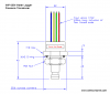
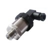
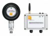
Featured strain gauge based measurement products

The two strain gauges that are pointing tangentially will be stretched across their width which will decrease the resistance. The other two strain gauges which are pointing radially will be stretched along their length which will increase the resistance.
Each strain gauges is then connected to the next one to form a diamond shape, and the points of the diamond become the connection points providing power to the circuit and for measuring the signal generated.
If a voltage supply is then applied across two opposite connection points of the Wheatstone bridge circuit, and a voltmeter is connected to the remaining two opposite connection points, a voltage drop will be detected which will vary depending on the stress applied to the surface that the wheatstone bridge circuit is mounted.
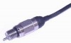
Featured strain gauge based measurement products
Help
I have red, black and white leads from strain gauges (SG) on the compression side of a cantilever beam. The resistance between the red & white lead and the black & red lead is 1K ohm. The resistance between the black & white lead is 2K ohms. How are the leads connected to the Wheatstone Bridge (WSB)? Are there 2 WSB’s? How do they connect? Please show a circuit diagram which has all four beam SG’s connected to a bridge and these to output circuit. Please identify typical discrete labeled components for an output of 0-5V.
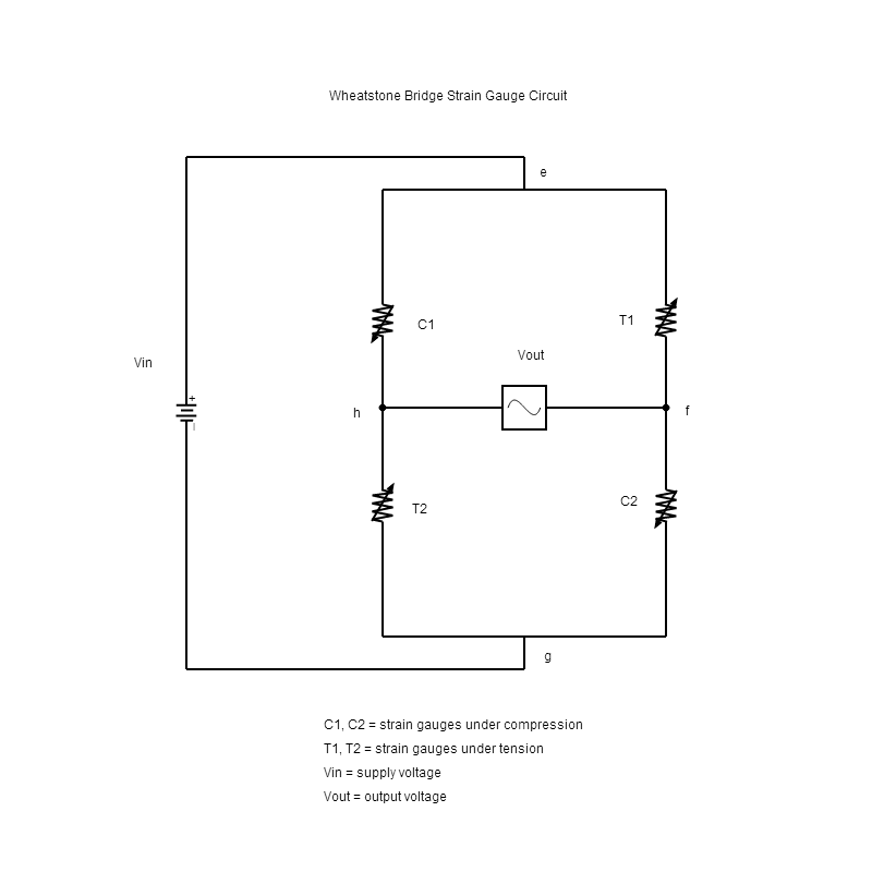
A wheatstone bridge typically has 4 strain gauges (see diagram above), of which 2 are under compression (C) and 2 are under tension (T). A circuit is formed by joining the strain gauges together end to end to create a loop in this order
C1 ↔ e ↔ T1 ↔ f ↔ C2 ↔ g ↔ T2 ↔ h ↔ C1.
If point ‘e’ is connected to a positive supply (supp+) and ‘g’ is connected to a negative supply (supp-), an equal current will flow through both sides of the loop if each of the strain gauges have equal resistance witout any strain applied.
If a strain is applied to the strain gauges, the resistance in C1 and C2 will reduce and T1 and T2 will increase. This create an imbalance between points ‘f’ and ‘h’ creating a potential difference (Vout) which is proportional to applied strain.
The output from a wheatstone bridge strain gauge circuit is typically a low voltage signal measured in millivolts. Therefore it is necessary to amplify the millivolt output with a strain gauge signal conditioning unit to generate an output of 0-5V.
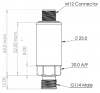
Featured strain gauge based measurement products
Related Technical Terms
- BFSG – Bonded Foil Strain Gauge
- Bourdon Tube
- Capacitive Fluid Level Measurement
- Ceramic Pressure Sensors
- Conductive Fluid Level Detection
- Doppler Effect Flow Measurement
- Float Fluid Level Detection
- LVDT – Linear Variable Differential Transformer
- Paddle Wheel Sensor
- Piezoresistive Strain Gauges
- Positive Displacement Flow Measurement
- Pressure Transducers
- Radar Distance Sensing
- SOI – Silicon on Insulator
- Strain Gauge
- Thin Film
- Transit Time Flow Measurement
- Turbine Rotor Sensor
- Ultrasonic Distance Sensing
- Ultrasonic Flow Velocity Sensors
- Vibrating Tuning Fork Fluid Level Detection
- Vortex Flow Measurement