
 In order for a 4-20mA current loop pressure transmitter to function within its designed performance levels a minimum voltage must be maintained across the two electrical connections to the device.
Since the electrical configuration is a current series loop circuit any load resistance added to the circuit will consume power resulting in a voltage drop across the component. This voltage drop must then be subtracted from the available voltage supply in order to determine the net voltage available for powering the pressure transmitter.
In many installations the instrumentation will take care of the load resistance and power supply considerations allowing the voltage supply specified to be used as the net available voltage for powering the pressure transmitter assuming no additional load is used in the circuit. However in installations where the power supply is separate to the measurement instrumentation the effect on available supply voltage due to a load resistor being added to the series current loop circuit should be considered.
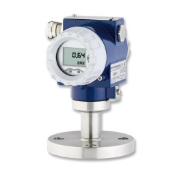
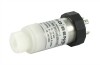
Featured pressure transmitter products

How does current loop signal affect supply voltage
The basic circuit for measuring the output of a current pressure transmitter is to connect a 24 Volt dc power supply, a 250 ohm precision load resistor and a pressure transmitter in series with each other. The analogue signal is measured indirectly by connecting a voltmeter across the load resistor which produces a voltage drop of 1 to 5 volt which is directly proportional to the 4 to 20 mA current loop (i.e. 250 ohms x 4/1000 amps = 1 volt, 250 ohms x 20/1000 amps = 5 volts). This effectively converts the current signal to a voltage signal which can be easily measured with a voltmeter or other signal conditioning instrumentation.
Determining minimum supply voltage
At the maximum signal of 20mA the voltage across the load resistor is 5 volts and this should be taken into account when determining how much voltage is left to power the current output pressure transmitter. In this case you would subtract 5 volts from the power supply of 24 volts, which would leave 19 volts available for powering the pressure transmitter. 19 volts is ample for powering most pressure transmitters. If a high load resistance is used, such as 500 ohms, then this would reduce the available supply voltage to 14 volts. Other causes of sensor supply voltage reduction are the running of the signal wires over very long distances so that the load contribution of the wiring becomes a significant consideration. Additional instrumentation such as an LED current loop display will also use up some of the power supply voltage. This calculator will assist you in determining the lowest supply voltages and the maximum load resistance to maintain operation of the current loop.
Determining maximum supply voltage
As well as being careful to provide the minimum required voltage it is also important to not exceed the maximum specified voltage, since this may lead to internal heating of the 4 -20mA pressure transmitter which could upset its performance characteristics. For example if the maximum supply voltage limit of the pressure transmitter is 28Vdc and the power supply produces 30 Vdc to the series loop circuit you would need to add a load resistance of at least 500 ohms in order to prevent the voltage across the pressure transmitter exceeding 28 Vdc at the minimum current of 4mA (i.e. 30 Volts – (500 ohms x 4/1000 amps) = 28V).
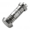
Featured pressure transmitter products
Manufacturer data sheets
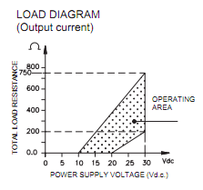 When examining a manufacturer’s technical data sheet for the required power supply be careful to determine which supply voltage they are referring to, since some times it will be the voltage required across the pressure transmitter and on others it will be the power supply voltage specified. On some product data sheets you may find a load diagram which shows the allowed region of operation for a given load and supply voltage.
Load resistor effect on pressure transmitter supply voltage
Below shows the voltage drop across a load resistor in a series current loop circuit at the minimum current of 4 mA and the maximum current of 20 mA. These values can be used to specify the power supply needed to ensure the pressure transmitter is powered by a supply voltage that is within its operational limits.
Subtract the values below from the power supply voltage to determine the highest and lowest voltage that is available to power the pressure transmitter.
| Ω | 4mA | 20mA |
|---|---|---|
| 50 | 0.2 | 1.0 |
| 100 | 0.4 | 2.0 |
| 150 | 0.6 | 3.0 |
| 200 | 0.8 | 4.0 |
| 250 | 1.0 | 5.0 |
| 300 | 1.2 | 6.0 |
| 350 | 1.4 | 7.0 |
| 400 | 1.6 | 8.0 |
| 450 | 1.8 | 9.0 |
| 500 | 2.0 | 10.0 |
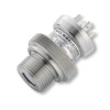
Featured pressure transmitter products
Related Help Guides
- How to get a 10 volt signal from a 4-20mA output pressure sensor
- How to Connect a 4-20mA Current Loop Pressure Transmitter
- What is difference between working, burst and over pressure
- How do you measure flow rate with a dp cell
- Choosing calibrator for pressure transmitters
- What can cause random variation in pressure transducer output
Related Technical Terms
Related Online Tools
- Pressure Transmitter 4-20mA Current Output Calculator
- Pressure Transmitter 0-20mA Current Output Calculator
Contact us about this Supply voltage and load resistance considerations for pressure transmitters page to request more information, or to discuss your application requirements.