
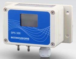
The DPS 300 is a low range HVAC differential pressure sensor for measuring pressure drops across air filters and airflow through and between ventilation ducts. The lowest possible pressure range is 0…100 pascals and the highest is 0…1000 millibars. User switchable 2 or 3 pressure ranges and volts or current output are included with most standard configurations.
The DPS 300 is a versatile, multi-range differential pressure transmitter specifically designed for dry, non-aggressive gases and compressed air across a variety of HVAC, clean room, and medical technology applications. Featuring an internal silicon diaphragm sensor with a limit point accuracy up to 0.5% FSO for ranges above 6 mbar , this transmitter supports user-switchable pressure ranges with up to three fields per device and switchable 3-wire output options (including 0…10 V and 4…20 mA) or a dedicated 2-wire setup. Highly adaptable, the device can be configured with an optional integrated two-line LC display, alarm contacts, automatic zero adjustment, and specialized square root extraction capabilities for direct airflow measurement tracking.
Product Parameters
- Pressure Range: 100 Pa up to 1000 mb differential
- Output Signal: 3 wire switchable 0-5/10 Vdc, 0/4-20mA or 2 wire 4-20mA
- Accuracy: 0.5% FS 6mb and above, 1% below 6 mbar
- Electrical Connection: screw terminals via M16x1.5 cable gland
- Process Connection: 6.6 x 11 mm, 4.4 x 10 mm or 4.4×10 mm for 4 mm tube fitting
- Media Compatibility: PVC silicone tube, brass nickel plated, ceramic, silicone, epoxy, RTV
- Environmental Protection: IP 54 ABS enclosure
- Special Features: Switchable pressure ranges and output signal
- Special Options: Alarm relay switches, auto-zero, square root extraction, LCD display
Product Description
The DPS 300 is an industrial-grade differential pressure transmitter purpose-built for surface or panel wall mounting within modern building management systems (BMS) and air handling units. By utilizing a high-performance piezo-resistive silicon sensor core combined with a ceramic substrate, the unit achieves exceptional long-term stability (up to ≤±0.2% FSO per year) and high overpressure protections across variable HVAC operational environments. Its core engineering highlight is a user-adjustable configuration structure; most standard models include a localized DIP switch panel enabling technicians to toggle among up to three distinct nominal pressure fields and switch between multiple current or voltage output signals in the field.
Each standard pressure range of 1.6, 4, 10, 40, 250, or 1000 mbar has one or two user selectable lower pressure ranges so that a number of dp sensors can stocked as spare and utilised for more than one pressure range.

The output signal can also be altered by the user to be either current or voltage output. As standard you can switch between 4 output configurations which include 0-5Vdc, 0-10Vdc, 4-20mA or 0-20mA. All of these output configurations are 3 wire, but you can also specify a non-switchable 2 wire 4-20mA version as well if necessary.
For complex monitoring configurations, the device offers an optional modular, five-digit backlit LC display with an integrated 52-segment analog bargraph. Operating through the internal menu system behind the front cover, users can manipulate parameters such as min/max peak tracking, custom pressure unit selection, and switch point delays. When specified with an integrated automatic zeroing valve, the transmitter performs automatic background adjustments to eliminate thermal drift errors, lowering maintenance costs over its 100-million load cycle operational lifespan. Furthermore, a specialized square root extraction mode (supporting linear, 3√, or 5√ curves) is available to convert raw static differential head pressures directly into volumetric airflow metrics.
Product Features
The DPS300 is designed for high-performance differential pressure monitoring, offering a suite of advanced features that prioritize operational flexibility, measurement precision, and long-term system reliability. From field-switchable signal outputs to automated zeroing and advanced flow calculation capabilities, these features ensure seamless integration into diverse HVAC, medical, and industrial control environments.
Multi-range Flexibility
The DPS300 offers exceptional versatility through its multi-range capability, allowing users to select up to three independent pressure ranges on a single device. This feature significantly minimizes inventory overheads for distributors and facility managers, as a single unit can be adapted to various operational requirements without the need for multiple specialized spare parts on hand.
Field-Switchable Analog Signals
Designed for rapid deployment and reconfiguration, the transmitter features field-switchable analog signals. Technicians can easily toggle between common industry standards, including 0…10 V, 0…5 V, 4…20 mA, and 0…20 mA loops. This adaptability ensures seamless integration into diverse control architectures, such as modern building management systems (BMS) or legacy PLC setups, without requiring hardware modifications.
Adjustable Damping Potentiometer
To ensure stable readings in dynamic environments like turbulent air ducts, the DPS300 includes an adjustable damping potentiometer. This allows for customizable response filtering times, ranging from near-instantaneous (0 msec) to heavily filtered (5000 msec). By smoothing out rapid pressure fluctuations or turbulence, this feature prevents signal noise, ensuring consistent and reliable data acquisition for control loops.
Configurable Limit Alarms
For enhanced system safety, the device supports optional integrated dual relay outputs or PNP open-collector contacts. These outputs deliver configurable limit alarms directly from the sensor, enabling immediate local switching or status indication. This reduces the complexity of system wiring by allowing the transmitter to serve as both a measurement instrument and a simple threshold monitor or safety interlock.
Automatic Zero Adjustment Circuit
Maintaining long-term precision is critical in static pressure applications. The integrated automatic zero adjustment circuit actively suppresses potential calibration drift over time, ensuring the baseline accuracy remains stable without requiring physical operator intervention. This reduces maintenance costs and downtime, particularly in hard-to-access locations, by preserving the sensor’s accuracy throughout its extended lifespan.
Advanced Square Root Extraction
The transmitter features advanced square root extraction profiles that enable the immediate calculation of volumetric flow rates using standard pressure-to-flow equations. By supporting linear, 3√, or 5√ curves, the device can directly output flow-related metrics, simplifying the integration of the transmitter into ventilation monitoring systems and eliminating the need for external signal processing or complex software conversions.
Robust Mechanical Construction
Engineered for durability in industrial and commercial settings, the DPS300 utilizes a rugged ABS housing that provides significant protection against environmental impacts. The design incorporates high-quality, brass nickel-plated barbs that offer superior mechanical resilience and reliable connections for pressure tubing, ensuring the device remains securely installed and operational even in demanding HVAC or process monitoring environments.
Product Applications
The DPS300 is engineered for versatile integration across a wide range of industrial and commercial environments, providing critical differential pressure measurement for airflow, filtration, and process control. From managing precise environmental conditions in clean rooms to optimizing heavy-duty ventilation and extraction systems, this transmitter delivers the stability and accuracy necessary to ensure operational efficiency, safety, and regulatory compliance across diverse pneumatic monitoring applications.
Duct Airflow Monitoring
Duct airflow monitoring is essential for maintaining optimal indoor air quality and energy efficiency in high-volume ventilation systems. By precisely tracking the differential pressure across airflow sensing elements, the DPS300 provides the accurate data required to balance supply and extract air volumes, ensuring that HVAC systems operate within their design specifications and maintain comfortable environmental conditions throughout the facility.
Filter Pressure Drop Tracking
Filter pressure drop tracking utilizes the transmitter to monitor the differential pressure across particulate filters, providing critical insights into their operational status. This continuous monitoring logs loading data in real-time, allowing facility managers to establish scheduled maintenance triggers based on actual filter performance rather than arbitrary time intervals. This proactive approach prevents system inefficiencies caused by clogged filters and extends the lifespan of downstream components.
Clean Room Technology Compliance
In clean room environments, strict pressure boundary control is paramount to prevent contamination and ensure product safety. The DPS300 enables precise monitoring of pressure differentials between isolated zones, ensuring that air flows in the correct direction—typically from cleaner to less clean areas. Its high stability and accuracy allow for the rigorous compliance required in pharmaceutical, semiconductor, and research facilities.
Draft Measurement Control Loops
For heavy-duty industrial extraction systems, boiler flues, and laboratory fume cupboards, the DPS300 is integral to draft measurement control loops. By accurately measuring the draft or negative pressure, the transmitter provides the necessary feedback for control systems to regulate fan speeds or damper positions. This ensures optimal combustion efficiency in boilers and maintains safety protocols in laboratory fume extraction systems by ensuring proper face velocity is maintained.
Medical Apparatus Design
The design of medical apparatuses often requires precise pneumatic control for dry, non-aggressive therapeutic gases. The DPS300’s reliability and measurement precision make it an ideal component for these systems, providing the accurate differential pressure data needed to manage gas flow, pressure stability, and patient safety. Its compliance with relevant standards ensures it can be safely integrated into various medical technology applications.
Fan Suction and Discharge Assessment
Fan suction and discharge assessment is crucial for optimizing the performance and safety metrics of air-source heat pump assemblies. By measuring the differential pressure across the fan, the DPS300 allows control systems to monitor fan health, detect blockages, and optimize the fan’s power curves for maximum energy efficiency. This assessment provides valuable diagnostic data that helps prevent equipment failure and ensures the overall reliability of the heating and cooling system.
Product Specifying Guide
Step 1: Select base pressure range requirement
Determine the maximum process boundary conditions and pick a nominal pressure model such as 1.6 mbar, 4.0 mbar, 10 mbar, 40 mbar, 250 mbar, or 1000 mbar. Each nominal option features user-selectable sub-ranges (e.g., the 4.0 mbar model can scale down to 0…2.5 mbar) to accommodate variable peak process demands seamlessly.
Step 2: Establish electrical configuration and output parameters
Choose between a flexible 3-wire standard loop configuration offering switchable 0…10 V, 0…5 V, or 4…20 mA channels, or a simplified 2-wire current loop limited strictly to a 4…20 mA output. Verify your available operating grid infrastructure supplies sufficient continuous voltage, noting that standard 3-wire topologies draw up to 30 mA, plus a further 23mA during intensive automated cycles for zero adjustment.
Step 3: Match accuracy thresholds and environmental attachments
Evaluate your systemic error limits; instruments measuring fields above 6 mbar naturally achieve an exact ≤±0.5% FSO limit-point accuracy, while lower fields operate within a ≤±1% FSO envelope. Next, map your tube diameters to choose the appropriate barbed physical porting interface, choosing either the standard 6.6×11 mm setup or the downsized 4.4×10 mm option.
Step 4: Specify modular accessories and display components
Decide if your site deployment dictates automated background zeroing loops or embedded localization readouts via a two-line LC display panel. Incorporating the screen unlock framework unlocks extended field parameter options, including dual alarm relay channels, customized measurement units, and custom mathematical transformation models.
Part Number Builder
Generate or decode DPS 300 ordering code
Configuration Rules & Restrictions
When selecting options for your DPS 300 Multi Range Differential Pressure Transmitter, please review the following technical constraints and automated interlocks. The configurator handles these rules in real-time to ensure your final ordering code represents a valid factory build.
Automated Accuracy Control
The instrument’s accuracy class is driven entirely by the selected Input Range and is automatically determined by the configurator:
- 2% FSO (Code: G): Enforced automatically for low-pressure ranges below 6 mbar (i.e., 0…1.6 mbar, 0…4.0 mbar, -1.6…+1.6 mbar, and -4.0…+4.0 mbar).
- 1% FSO (Code: 8): Enforced automatically for standard pressure ranges 6 mbar and above (including all higher positive and symmetrical/bi-directional ranges).
- Note: The Accuracy dropdown is locked from manual selection as it is strictly dependent on the physical pressure capsule chosen.
Forced Display Interlocks (Contacts & Processing)
The inclusion of physical control switches or mathematical flow conversion modules requires an integrated interface for monitoring and parameterization:
- Selecting 2 contacts with LC display (Code: B) under Contact OR selecting Square-root extraction with LC display (Code: 605) under Special Version will automatically override, lock, and force the Display dropdown to LC display (Code: C).
- When either option is chosen, the “Without display (0)” selection is completely hidden and disabled. Unselecting these options will immediately unlock the display field and make the standard non-display model available again.
Symmetrical Range Constraints
Symmetrical (bi-directional) ranges cross through zero into negative compound pressure (e.g., -10…+10 mbar or -1000…+1000 mbar). Due to manufacturing limits on signal processing configurations:
- Contacts are Permitted: You can combine 2 contacts with LC display (Code: B) with a symmetrical input range, provided the integrated LC display is active.
- Square-Root Extraction is Prohibited: The Square-root extraction with LC display (Code: 605) module cannot calculate values across zero into a negative pressure profile. Therefore, if a symmetrical range is chosen, Code 605 is automatically disabled and hidden from selection, and the Special Version field safely resets to Standard (Code: 000).
Installation & Operation Guide
Step 1: Physical enclosure orientation and alignment
Securely fasten the transmitter housing onto a flat, vibration-free surface panel using the dual integrated external mounting tabs. Ensure the unit maintains a vertical installation orientation with the barbed connection barbs pointing directly down; this prevents zero-point measurement offset deviations and mitigates gravity-assisted condensation collection inside the tubing.
Step 2: Pneumatic tube porting connections
Examine your relative pressure streams and route the tube handling your high-pressure source cleanly onto the right-hand positive (+) barb connector. Attach your low-pressure or reference suction tube onto the left-hand negative (-) barb connector, ensuring there are no sharp bends, pinches, or mechanical kinks across the flexible PVC or silicone pipe lines.
Step 3: Electrical loop wiring termination
Loosen the case cover screws to expose the primary circuit block, then guide your power and signal wiring securely through the strain-relieved M16x1.5 cable gland. Wire the incoming bare conductors directly to the designated numbered terminals—such as Terminal 8 for positive supply (+) and Terminal 7 for negative supply (-) in a 3-wire setup—before re-tightening the gland and housing shield by hand.
Step 4: Internal DIP switch calibration and warm-up
Set the four-pole internal CONFIG slide assembly positions to align your desired operating span and active output scale according to the specification tables. Energize the electrical grid circuit and allow the electronic components to stabilize through a full 30-minute thermal warm-up window before executing any manual zero-point potentiometric adjustments or digital overrides.
Product Help
Bidirectional tracking configuration
Can the sensor be deployed to monitor both suction and discharge pressures simultaneously?
Yes, the device can be specified with a bidirectional or compound pressure span, such as -40…40 mbar, allowing it to register positive and negative pressure deviations across the central zero baseline. For standard positive-only configurations, a negative relative pressure (down to -3 mbar) can also be tracked by routing the vacuum line to the negative process port while leaving the positive port open to atmosphere.
Response delay tuning
Is it possible to adjust the output response time to handle pressure surges in turbulent air ducts?
Yes, the transmitter features an adjustable damping circuit that allows users to modify the 90% response time from its default state of less than 100 msec up to a heavily filtered 5000 msec. Technicians can easily tune this parameter manually by inserting a size 2 Phillips screwdriver into the dedicated mechanical potentiometer located on the main circuit card.
Minus 3 mbar range
We need -3 mbar to 0 mbar relative, is this possible?
Yes you can do that with fixed 0 to 3 mbar differential range, just connect to what you are measuring (-3mbar) to the negative port, and leave the positive port open to ambient atmosphere (relative).
Thermal drift management
How do I address minor baseline deviations or drift caused by changing ambient building temperatures?
Minor zero-point errors can be corrected after a 30-minute warm-up window by keeping both pneumatic ports open to atmosphere and adjusting the internal zero-point potentiometer until the analog signal reads true nominal zero. Alternatively, choosing a model equipped with the integrated zeroing valve automates this step by running routine background adjustments every 24 hours or 7 days via internal configuration switches.
100 pascal range with 2 pascals accuracy
We require the pressure transmitter to operate with a range of at least 0 Pa to 100 Pa, and an accuracy of ±2Pa?
The DPS 300 quoted below has a dual range and the lower one of the two is 0 to 1 mbar / 100 Pa, which has an accuracy of 1% FS or 1 pascal.
1 sec response time
We need the output to have a 90 % response time of 1 second or better?
The 90% response time is < 100 ms; adjustable by potentiometer in the range of 0 msec up to 5000 msec.
Volumetric airflow calculations
Can this instrument calculate volume flow velocities directly instead of just registering raw differential head pressure?
Yes, when configured with the optional two-line LC display, the transmitter can activate an integrated square root extraction transfer function. This allows the user to select linear, 3√, or 5√ output curves to cleanly convert raw pressure differentials into direct flow metrics using common structural pressure-to-flow equations.
Fan suction pressure differential
I am looking for a low differential pressure transmitter to measure the suction pressure produced by a fan in an air source heat pump. The range of suction pressure that we are producing is approximately up to 50Pa?
The DPS300 quoted below can be switched between 0-100 PA and 0-160 Pa, so if the pressure happens to be more than 50 Pa, you should be able to re-range and measure pressure 3 x higher without switching to another instrument.
There is also the option for a 2 wire 4-20mA instead of 3 wire 4-20mA, but you lose the convenience of being able to switch to other output types.
- SKU ID: s1-dps300-2-45673
- Part No: 815-0016-3Z-0-G-0-N-Y00-M-000
- Pressure Range: 0 to 1.6 / 0 to 1 (2 switchable ranges)
- Units: mbar
- Range Type: Differential (0 to +P)
- Output Signal & Supply Type: 0 to 10 Vdc / 0 to 20 mA / 0 to 5 Vdc / 4 to 20 mA (3 wire, 4
- switchable outputs)
- Output Options: Linear
- Supply Voltage: 19-32Vdc
- Accuracy (linearity only): 1% full scale
- Electrical Connection: M16 x 1.5 cable gland
- Process Connection: 6.6mm dia x 11mm barbed connections
- Media Compatibility: Air
- Optional Extras: None
Absolute pressure deployment restrictions
Can I use this differential sensor for tracking absolute pressure or in open-air transport scenarios?
This device is exclusively designed for gauge and differential measurements of dry, non-aggressive gases and must not be used for absolute pressure tracking. During transportation or logistical relocation, ensure both physical pressure ports are fully open to local ambient atmosphere to prevent severe kinetic overpressure damage to the internal silicon sensor element.
Custom pressure ranges
From the data sheet I understand the DPS300 is a multi-range differential pressure transmitter. In that case, I presume we could use one model for all the measurements required for our measurements from 1.5mbar to 7mbar, or would you suggest using multiple sensors with 10mbar model for measurements from 6mbar to 7bar, 4mbar model for measurements from 2.5 to 4mbar and 1.6mbar model for measurements from 1mbar to 1.6mbar.
The multi-range capability is limited to 1 or 2 other fixed ranges (see pressure range table above). The ranges you have specified would have to supplied as single fixed custom pressure ranges since none of them correspond to a switchable range. The custom pressure range version cannot be altered by the user in the same way as the standard ranges.
Suction & discharge
Can the sensor could be used for both suction and discharge?
Yes, but you have to specify a bidirectional or compound pressure range such as -40 to + 40 mbar.
DMP 343 vs DPS 300
What is the difference between the two models DMP 343 and DPS 300?
The DMP 343 is a gauge reference pressure range (one port) device only, and minimum range is 10 mbar, whereas the DPS 300 is a gauge/differential pressure range (2 ports) device with minimum range of 1 mbar.
Related Documents
Specification data sheet
Request Product Price
"*" indicates required fields