
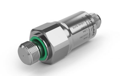
The TPLA series pressure transmitter utilizes a high-precision silicon piezoresistive sensing element designed for exceptional sensitivity and long-term stability, particularly in low-pressure applications. Constructed with stainless steel AISI 316L wetted parts and a durable AISI 304 housing, this series is engineered to withstand demanding industrial environments while maintaining an accuracy of better than ±0.5% FS. With a broad range of configuration options including various amplified analog outputs, multiple process connections, and integrated pressure peak protection, the TPLA offers a versatile solution for precise pressure monitoring from 50 mbar up to 60 bar.
Product Parameters
- Measurement Range: 0…0.05 bar to 0…60 bar
- Output Signal: Amplified voltage (e.g., 0-10V, 1-5V) or current (4-20mA)
- Accuracy: Less than ±0.5% Full Scale at room temperature
- Process Material: Stainless steel AISI 316L for wetted parts
- Housing Material: Stainless steel AISI 304
- Ingress Protection: IP65 to IP67 depending on the connector and installation
- Temperature Limits: Process temperatures from -40 to +125°C
- Sensing Technology: Piezoresistive silicon sensing element with silicone oil fill
Product Description
The TPLA series represents a high-performance advancement in piezoresistive pressure measurement, specifically engineered to deliver reliable data in processes where precision at low pressure is critical. By employing a silicon sensing element, the transmitter achieves high levels of repeatability and low hysteresis, ensuring that measurements remain consistent over extended operating periods. The internal electronics provide a range of amplified analog signals, making these units compatible with standard industrial PLCs and control systems.
Durability is a core feature of the TPLA design. The use of AISI 316L stainless steel for wetted parts and FKM seals ensures compatibility with a wide variety of fluids and gases. For applications subject to hydraulic shock or cavitation, such as those involving fast-acting valves or pump starts, the series can be equipped with an optional integrated pressure snubber. This 0.5 mm diameter through-hole effectively dampens harmful pressure peaks, protecting the sensing element from mechanical failure.
Configuration flexibility allows for seamless integration into existing hardware setups. The series supports five standard mechanical process connections, including G 1/4 and G 1/2 threads, and four distinct electrical connection styles such as M12x1 and various EN 175301-803 connectors . Each unit is manufactured to comply with international standards, including EMC and RoHS directives, and is available with both absolute and relative pressure measurement options.
Product Features
- High sensitivity silicon piezoresistive technology for low-range accuracy.
- Wide selection of output signals including current and multiple voltage ranges .
- Optional integrated pressure snubber for protection against liquid hammer and cavitation.
- Robust stainless steel construction with AISI 304 housing and AISI 316L wetted parts.
- Excellent long-term stability with less than 0.2% FS drift per year.
- High overpressure and burst pressure ratings for enhanced safety .
- Multiple electrical termination options including M12, DIN connectors, and direct cable output.
- Wide operating temperature range for both process fluids and ambient environments.
Product Applications
- Food and pharmaceutical packaging machinery requiring precise low-pressure control.
- Industrial inkjet printers and dosing systems for fluid management.
- Extrusion blow moulding equipment for consistent material processing.
- Hydraulic systems where pressure peaks and cavitation protection are required.
- General industrial process monitoring requiring high-accuracy analog feedback.
- Laboratory and measurement equipment for research and development.
Product Specifying Guide
Step 1: Select Output Signal
Choose the analog output that matches your control system requirements. Standard options include 4-20 mA current loops (Code E), 0-10 Vdc voltage (Code N), or 1-5 Vdc voltage (Code P). Numerous other voltage variants such as ratiometric 0.5-4.5 V are available on request .
Step 2: Choose Process Connection
Identify the thread type required for your pressure port. The series offers five standard options including G 1/4 (E1) or G 1/2 (31) ISO 1179-2 connections with rubber seals, as well as EN 837 (35) and DIN 3852 (12) versions .
Step 3: Define Electrical Connection
Select the termination style for your wiring. The M12x1 4-pin connector (Code Z) is standard for high ingress protection, while the EN 175301-803 Form A (E) and Form C (C) connectors are common for industrial valve-style cabling. A 1-meter direct cable output (F) is also available .
Step 4: Specify Measurement Range and Type
Select your pressure range from 0.05 bar (BV05) up to 60 bar (B06D). You must also specify whether you require a Relative (G) measurement for gauge pressure or an Absolute (A) measurement for pressure relative to a vacuum .
Step 5: Select Additional Options
Determine if your application requires an integrated snubber (Code S) for pressure peak protection. You can also specify transducer cleaning for specific purity requirements and whether a formal calibration report is required for your quality documentation.
Part Number Builder
Generate or decode TPLA ordering code
Installation & Operation Guide
Step 1: Physical Mounting
Screw the transducer into the pressure port using the hex flats (typically 24mm or 27mm depending on the model). While mounting position effects are generally negligible, it is best practice to install the unit in a location where it is protected from excessive vibration and accidental physical impact.
Step 2: Electrical Grounding
Ensure the transducer is properly grounded through the machine body. This is the primary method for maintaining the required protection level and ensuring accurate signal transmission.
Step 3: Wiring the Signal
Connect the shielded cable according to the connection diagram for your specific output type. For voltage versions (3-wire), connect supply +, supply -, and signal. For current versions (2-wire), the sensor is connected in series with the current loop. Ensure the cable shield is grounded only at the PLC side.
Step 4: Powering the System
Verify that the supply voltage is within the specified range (typically 8-30 Vdc) before powering on. The unit has a short warm-up time of less than 30 seconds before it reaches rated performance. The electronics include reverse polarity protection to prevent damage during initial setup.
Product Help
Measurement type selection
What is the difference between relative and absolute pressure versions in this series?
Relative pressure (G) measures pressure relative to atmospheric pressure, whereas absolute pressure (A) measures pressure relative to a perfect vacuum. For the TPLA series, absolute pressure is available as a standard option for ranges at or above 1 bar, and is the only option for ranges 4 bar and higher.
Using the pressure snubber
When should I specify the optional integrated pressure snubber?
The pressure snubber (option S) is recommended for hydraulic applications where the system may experience “liquid hammer,” cavitation, or rapid pressure spikes caused by the sudden starting/stopping of pumps or fast-closing valves. The 0.5 mm diameter orifice dampens these peaks to prevent damage to the sensing element.
Grounding and shielding requirements
How should the electrical shielding be handled during installation?
To ensure signal integrity and prevent electromagnetic interference, you must use a shielded cable. The cable shield should be grounded on the PLC/instrument side and left floating on the machine side. The transducer itself must also be grounded, typically through the machine body or the equipment it is threaded into.
Output load limits
How do I calculate the maximum load resistance for the 4-20mA current version?
The total load resistance (RL) is dependent on the power supply voltage. You can calculate the maximum allowed resistance using the formula RL≤(V supply −10V)/0.02A. For example, with a 24V supply, the maximum load would be 700 ohms.
Environmental protection ratings
What ingress protection (IP) rating can I expect once installed?
The IP rating depends on the chosen electrical connector. The M12x1 (Z) version provides IP67 protection when the female connector is properly mounted and tightened. The EN 175301-803 connectors (E and C) provide IP65 protection. In all cases, the rating only applies when the mating connector is correctly plugged in and wired.
Related Documents
Specification data sheet
Request Product Price
Please select the options you require for the TPLA Low Range Industrial Pressure Transmitter in your application and request a quote.