
Featured pressure calibration products
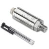 Zero & Span calibration adjustable signal output pressure transducers - Pressure transducers that have an adjustable zero and span so that the output siganl can be adjusted if they go slightly out of calibration
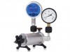
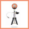 Suction Pressure Calibration Equipment - Select a calibration equipment for calibrating suction pressure measuring devices, and generating suction pressure for setting calibration points.
User Guide
This calibration error calculator can be used to determine the accuracy of measurement devices which have a linear input and output characteristic. The error is calculated by determining the difference between the actual output measured and the ideal output for a particular input value.
Input
Input Reading
Enter the input value measured/recorded with a calibrator or other reference instrument that has a higher accuracy than the device under test. It is important that all input values are entered in the same engineering units.
Lowest Input
Enter the lowest possible input value that the unit under test was designed to measure. It is important that all input values are entered in the same engineering units.
Highest Input
Enter the highest possible input value that the unit under test was designed to measure. It is important that all input values are entered in the same engineering units.
Output
Output Reading
Enter the output value measured/recorded with a calibrator or other reference instrument that has a higher accuracy than the device under test. If the output of the device under test is a visual display then use the displayed measurement. It is important that all output values are entered in the same engineering units.
Lowest Output
Enter the lowest possible output value that the device under test was designed to produce. It is important that all output values are entered in the same engineering units.
Highest Output
Enter the highest possible output value that the device under test was designed to produce. It is important that all output values are entered in the same engineering units.
Error
Ideal Output
This shows the theoretical output reading that would be produced if the device under test was perfectly precise. This value is compared to the actual “Output Reading” to determine the output “Error Value” of the device under test at a particular calibration point.
Error Value
This represents the difference between the actual “Output Reading” and the “Ideal Output” and is shown in the same engineering units as the output.
%FS Value
This displays the output error as a percentage of the full scale range i.e. the “Error Value “divided by the difference between “Lowest Output” and “Highest Output.”
Help
Defining full scale for compound & bi-directional pressure range errors
I was wondering what full scale you would use for the following pressure sensor ranges:
- -1 to +1 bar
- 800 to 1200 millibar
- -1 to +1.5 bar
Method A
In the context of the calibration error calculator, the full scale is determined by subtracting the maximum pressure from the minimum pressure:
- 2 bar
- 400 mbar
- 2.5 bar
Method B
Alternatively some manufacturers will define the accuracy based on the range from zero pressure to the maximum positive or negative pressure, whichever is the greatest, since this represents the base range of the sensor:
- 1 bar
- 1200 mbar
- 1.5 bar
As a further example a -1 to =0.5 bar range might use 1 bar rather than 1.5 bar for defining the accuracy, since the sensing diaphragm will be rated to that pressure.
The absolute error is of course always going to be the same, but when expressed as a percentage error it is important to use the same full scale when comparing your own to the manufacturer’s percentage error values.
Manufacturer’s Full Scale
So you have to be careful when determining the pass/fail error value for the total span of a manufacturer’s specification, because this is not always clearly defined for compound and bidirectional ranges.
If the full scale limits are not clearly defined by the manufacturer, then it is best to assume the manufacturer is using method ‘A’. This will ensure you are using the worst case error for the sensor, when assessing whether it meets your required accuracy. The downside is that you may choose not to use a particular sensor because the assumed error is too large.
Featured pressure calibration products
 Vacuum Range Calibration Equipment - Maintain the accuracy of your vacuum sensors, gauges, and switches with high-quality vacuum calibration equipment.
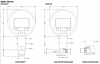 DM01-500-HD High Range Digital Pressure Gauge - The DM01-500 HD high range pressure gauge is available in pressure ranges from 0 to 600, 1000, 1600, 2000 & 2200 bar.