
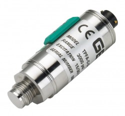
Flush diaphragm pressure transmitter for high viscosity media in food processing and plastic injection moulding applications.
The TPFADA series is an advanced flush diaphragm pressure transmitter engineered for precise pressure measurement in challenging industrial environments involving high-viscosity, thick, or abrasive media where traditional internal measuring chambers are prone to clogging. Built upon bonded strain gauge on stainless steel technology with four active arms, the transmitter features a robust 17-4PH stainless steel flush-fitting measuring diaphragm with a thickness of up to 2.2 mm housed within a compact Ø26.5 mm body. Covering broad measurement ranges from 0…10 to 0…1000 bar (0…150 to 0…15000 psi) with an accuracy of up to ±0.2% FSO typical, the transmitter delivers rapid dynamic performance with response times under 1 msec. It integrates digital signal conditioning that enables seamless non-intrusive zero and span adjustment via an included magnetic pen, alongside an internal 80% FSO calibration signal generation, making it an optimal solution for demanding process control and OEM applications.
Product Parameters
- Pressure Ranges: From 0-10 to 0-1000 bar (0-150 to 0-15000 psi)
- Accuracy: 0.3% FS for ranges from 60 up to 1000 bar, 0.6% FS for ranges from 10 up to 50 bar
- Output Signals: 4-20 mA (2-wire), 0-10 Vdc, 0.1-5.1 Vdc, 0.1-10.1 Vdc, 0-5 Vdc, 1-5 Vdc, 1-6 Vdc, and 1-10 Vdc
- Response Time: Fast dynamic response of less than 1 msec (10…90% FSO)
- Operating Media Temperature: Process fluid range from -40…+120°C (-40…+248°F) with a compensated thermal range of -10…+85°C (+14…+185°F).
- Electrical Connections: 6 pin military bayonet, DIN plug & Binder 7 pin with IP65, 66 or 67 protection ratings
- Pressure Connections: M18 x 1.5, 3/4-16 UNF, G1/2 male with flush diaphragm
- Media Compatibility: 17-4PH stainless steel wetted flush diaphragm and AISI 304 stainless steel sensor housing.
- Special Features: R-Cal shunt calibration signal, auto zero & span calibration setting via magnetic pen
Product Description
The TPFADA series flush diaphragm pressure transmitter is specifically designed for applications where standard pressure transducers with internal cavities or narrow pressure ports cannot function reliably due to media build-up or clogging. Utilizing a Wheatstone bridge configuration with four active arms bonded directly onto a stainless steel structure, the transmitter converts mechanical strain into a highly linear, low-noise analog signal. The primary wetted element consists of a heavy-duty 17-4PH stainless steel flush diaphragm, manufactured with wall thicknesses up to 2.2 mm, offering superior resilience against abrasive particles, mechanical shock, and pressure surges.
At the core of the TPFADA series is an advanced digital microprocessor-based signal conditioner. This digital architecture replaces traditional analog potentiometers and trimmers, eliminating vulnerability to vibration drift and moisture intrusion. The integrated “Digital Autozero & Span” system allows field technicians to execute precise zero-point re-referencing and full-scale span recalibrations directly on the installed unit. These adjustments are performed magnetically through the stainless steel housing using the standard PKIT 312 magnetic pen, maintaining complete ambient seal integrity. Additionally, selected models support an internal 80% Full Scale Output (FSO) shunt calibration function triggered via dedicated pin connections, enabling remote verification of acquisition hardware without applying process pressure.
The mechanical design emphasizes extreme compactness and ease of installation. Featuring a reduced body diameter of Ø26.5 mm and an integrated 27 mm hexagonal wrench flat, the sensor simplifies mounting in tight manifold blocks and machinery recesses. Electrical connectivity options include M12x1 4-pole circular connectors, 6-pole bayonet connectors, 7-pole threaded connectors, DIN EN 175301-803 Solenoid/Micro-Solenoid plugs, and direct shielded cable outlets. Every TPFADA unit features indelible laser-marked product data on its stainless steel housing, ensuring long-term traceability in harsh industrial environments.
Flush diaphragm
Engineered for longevity, the transmitter utilizes a heavy-duty 17-4PH stainless steel flush measuring diaphragm, boasting a substantial thickness of up to 2.2 mm. This robust construction is specifically designed to prevent media accumulation, effectively mitigating the risks associated with clogging in industrial processes. By eliminating internal cavities, the sensor maintains operational integrity even when exposed to thick, abrasive, or challenging fluids, ensuring reliable performance over extended service lives.
Measuring the pressure of high viscosity fluids that congeal at low temperatures is likely to lead to problems with pressure sensors that have recessed diaphragms. In applications such as measuring the pressure of paper pulp, adhesives or plastic moulding material, a standard pressure connection is likely to clog especially when the process is switched off and the temperature drops or the media dries out. When the process is switched back on the pressure sensor may take some time to start measuring the true pressure if at all due to a slug of solidified process media preventing the pressure being transmitted to the diaphragm. A flush diaphragm makes it possible to measure the pressure of high viscosity process media without the risk of media becoming trapped.
Process fittings
The TPFADA flush diaphragm pressure sensor have screw-in style pressure fittings so that they can be installed in locations where space is limited or there is small diameter pipe work. There is a choice of threads that can be specified M18 x 1.5, 3/4-16 UNF and G1/2 male. Both pressure sensors have polished 17-4ph stainless steel wetted parts and the exposed diaphragms are completely flat with no convolutions or crevices.
Pressure ranges
The TPFADA flush pressure sensor can measure the pressure of most corrosive fluids from 150 psi up to 15,000 psi gauge.
Sensing principle
The pressure sensing technology employed is bonded foil strain gauge, which is highly robust and reliable for high duty cycle applications.
Output signal
The TPFADA flush pressure sensor has a 4-20mA signal for use in process control systems in paper mills or adhesive & sealant manufacturing and a selection of amplified voltage output such as 0-5V, 0-10V and 1-5V for use in plastic extrusion and moulding machines.
Non-Intrusive Magnetic Adjustment
The integrated Digital Autozero & Span technology represents a significant leap in field maintainability. This system allows technicians to perform complete zero-point and span alignments without ever compromising the sealed enclosure. By utilizing a simple magnetic pen against the housing, users can achieve precise recalibration while maintaining complete protection against moisture, dust, and environmental contamination.
Ultra-Fast Dynamic Response
With a rapid response time of less than 1 msec (10…90% FSO), this series is optimized for the most demanding applications. This high-speed performance is essential for real-time monitoring of rapid transient events, such as those found in high-speed hydraulic systems and precision injection molding cycles, where every millisecond of data resolution is critical for process stability.
Integrated Shunt Calibration
Efficiency in maintenance is streamlined through the internal 80% FSO calibration signal generation. This feature enables rapid, end-to-end signal path testing—without the need to apply actual process pressure. By verifying the integrity of the downstream acquisition hardware and wiring, operators can confirm system calibration quickly, reducing downtime on 6-pole, 7-pole, and cable-equipped versions.
Product Applications
High-Viscosity Fluid Monitoring
This transmitter is exceptionally well-suited for industrial processes that involve high-viscosity media such as thick oils, heavy greases, resins, adhesives, and polymers. Its robust flush diaphragm design prevents the clogging and media buildup commonly associated with traditional pressure ports, ensuring continuous, reliable measurements in challenging, viscous environments.
Chemical and Process Media Processing
Designed for the rigors of chemical manufacturing, this sensor excels in monitoring aggressive process media, including various pulps, polyurethane, bitumen, tar, and complex slurry lines. The durable stainless steel construction provides the necessary chemical resistance to maintain performance and structural integrity despite prolonged exposure to harsh or corrosive substances.
PU sealant
Measure the pressure of Polyurethane (PU) sealant.
- SKU ID: s1-tpfada-0001
- Part No: TPFADA-E-M-Z-B05D-M-V
- Pressure Range: 0-50
- Units: bar
- Range Type: Gauge (atm to +P)
- Output Signal: 4-20mA
- Electrical Connection: M12 x 1 connector
- Optional Mating Connectors: Not required
- Process Connection: G1/2 with flush diaphragm
Rubber and Plastics Injection Machinery
The TPFADA series is engineered to provide precise, real-time pressure acquisition in demanding high-speed hydraulic injection units and extrusion manifolds. By accurately capturing rapid pressure changes, the transmitter enables tighter process control and consistent product quality during the intensive cycles characteristic of modern plastic and rubber manufacturing.
Food, Beverage, and Food-Grade Oil Systems
The unit is an ideal choice for food, beverage, and sanitary oil systems that require clean, non-clogging flush mounting interfaces. Its design allows for hygienic integration, ensuring that viscous food-grade fluids and pastes can be monitored accurately without creating stagnation points or accumulation risks that could compromise process hygiene.
Heavy Hydraulic Systems and Presses
Engineered for durability, this transmitter offers reliable pressure monitoring for high-pressure hydraulic presses, cylinders, and fluid power equipment. Its ability to withstand intense pressure spikes and rugged operating conditions makes it a critical component for maintaining safety and efficiency in heavy-duty industrial machinery.
Product Specifying Guide
Select the output signal
Determine the required electrical output signal matching the system controller or PLC input card. Standard selections include 4…20 mA 2-wire current loops (Code E) or 0…10 Vdc voltage outputs (Code N). Additional option codes include 0.1…5.1 Vdc (Code B), 0…5 Vdc (Code M), 1…5 Vdc (Code P), 1…10 Vdc (Code Q), 1…6 Vdc (Code R), and 0.1…10.1 Vdc (Code C).
Select the process connection
Choose the appropriate flush diaphragm process connection style based on mounting port specifications. Available standard options are M18x1.5 male (Code G) and 1/2″ G male (Code M). For specialized manifolds, a 3/4-16 UNF thread (Code L) is available upon request.
Select the electrical connection interface
Specify the electrical interface based on IP protection requirements and functional capabilities. Options include a 6-pole bayonet connector (Code V, IP66), a 7-pole connector (Code P, IP67), an M12x1 4-pole male connector (Code Z, IP67), a 4/6-pole shielded cable (Code F, IP65), an EN 175301-803 Type A solenoid plug (Code E, IP65), or an EN 175301-803 Type C microsolenoid plug (Code M, IP65). Note that the 80% FSO Calibration function and Autospan feature are available on 6-pole (V), 7-pole (P), and shielded cable (F) configurations.
Define the pressure measurement range
Select the required full-scale pressure range in either bar or psi units. Bar ranges extend from 0…10 bar (Code B01D) up to 0…1000 bar (Code B01M), including common steps such as 0…16 bar (B16U), 0…50 bar (B05D), 0…100 bar (B01C), 0…250 bar (B25D), and 0…400 bar (B04C). Psi options cover 0…150 psi (P15D) up to 0…15000 psi (P15M).
Part Number Builder
Generate or decode TPFADA ordering code & request quote
Installation & Operation Guide
Mechanical mounting and torque application
Verify that the process mating port is clean, burr-free, and dimensionally aligned with the flush diaphragm profile. Install the sensor into the process tap using an appropriate sealing washer or ring. Apply force exclusively to the 27 mm hexagon wrench flats located on the sensor body using a calibrated torque wrench. Tighten to a maximum installation torque of 40 Nm, ensuring not to apply stress directly to the upper housing or connector casing.
Electrical wiring and grounding procedures
Connect the sensor using high-quality shielded cable with cable lengths strictly under 30 meters. Ensure the sensor housing is bonded to equipment ground, typically accomplished through direct metal-to-metal contact with the machine body. Connect the cable braid/shielding to the connector casing on the sensor end while leaving the braid floating (unconnected) at the PLC/instrument end to prevent ground loop noise. Route signal wiring separately from high-voltage or power cables to prevent electromagnetic interference.
Executing Autozero zero-point alignment
To perform zero adjustment after mechanical installation, ensure the process pressure is at atmospheric pressure (0 bar relative) and the sensor is at stable operating temperature. Position the PKIT 312 magnetic pen against the target marked “Autozero” on the stainless steel housing and hold it in place for 1 to 10 seconds. Remove the pen; the zero adjustment takes effect within 2 seconds, correcting zero imbalances within ±10% FSO. During activation on 4…20 mA models, signal current briefly increases by approximately 7 mA before stabilizing at 4.00 mA.
Executing Fine-Autozero adjustment
When high-precision zero trimming is required, place the magnetic pen over the “Autozero” target area for 10 to 30 seconds, then remove it. The transmitter will begin scrolling its output signal step-by-step in increments of 6 mV for voltage outputs or 12 µA for current outputs every 5 seconds. When the desired zero value is observed on the measurement instrument, touch the magnetic pen against the Autozero area once more to lock in the setting.
Activating internal calibration shunt function
For models equipped with 6-pole (V), 7-pole (P), or shielded cable (F) interfaces, activate the 80% FSO calibration check by short-circuiting the dedicated CAL contacts (pins E-F on 6-pole, pins 5-6 on 7-pole, or blue-orange wires on cable version) for a minimum of 1 second. Within 2 seconds, the output signal will step to 80% of Full Scale Output to verify receiver scaling. Release the short circuit to return the unit to standard measurement mode.
Product Help
How to perform autozero adjustment
How is the zero point adjusted after installing the TPFADA pressure transmitter?
The zero point is adjusted digitally without opening the sensor enclosure by using the supplied magnetic pen. With the process line at zero pressure and normal operating temperature, hold the magnetic pen against the “Autozero” symbol on the sensor body for 1 to 10 seconds. Upon removing the pen, the internal electronics automatically correct any zero offset within ±10% FSO, setting the output to 4.00 mA or 0.00 Vdc.
Restoring factory default calibration settings
How can factory default zero and span settings be restored if calibration values become corrupted?
Factory settings can be restored using the magnetic pen applied to the “Autozero” label. Holding the magnet in position for 30 to 60 seconds triggers a Partial Reset, which restores the factory zero baseline while performing an automatic zero sequence without altering span. Maintaining contact for more than 60 seconds triggers a Total Reset, which completely restores both zero and full-scale span calibrations back to original factory defaults.
Cable shielding and grounding recommendations
What are the grounding and cabling requirements to protect signal integrity?
Installations require a high-quality shielded cable. The transmitter body must be grounded through its process connection to the machine chassis. The cable braiding/shield must be electrically connected to the connector shell at the sensor end and left floating (unconnected) at the PLC or controller end to prevent ground loops. Always run signal cables away from high-voltage lines and motor drives.
Operating range limits for digital autospan adjustment
What are the allowable limits and prerequisites for performing an Autospan calibration?
The Digital Autospan feature allows full-scale span adjustment within a maximum limit of ±5% FSO. To execute Autospan on supported models (6-pole, 7-pole, or cable versions), first perform an Autozero at 0 bar pressure. Next, apply a known reference pressure equal to Full Scale (within ±5%), short-circuit the CAL contacts, hold the magnetic pen on the Autozero area for 1 to 10 seconds, and release the CAL short-circuit. Finally, return the pressure to 0 bar and execute a second Autozero.
Maximum allowable installation torque and mechanical precautions
What is the maximum torque permitted when screwing the sensor into a process fitting?
The maximum recommended installation torque is 40 Nm. Tightening torque must be applied strictly to the 27 mm hexagonal surface integrated into the stainless steel lower body using an appropriate open-ended or socket wrench. Force must never be applied to the cylindrical upper housing or connector assembly, as this can permanently damage internal electronics and housing seals.
Related Documents
Specification data sheet
Operating manual
Request Product Price
Please select the options you require for the TPFADA Flush Diaphragm Pressure Transmitter in your application and request a quote.