

The industrial pressure transmitter, IMP, has a piezoresistive ceramic pressure sensor giving it excellent media compatibility. The housing is made from stainless steel with a choice of internal O ring seals to select to ensure the product is suitable for a wide range of applications. Every device is temperature compensated and calibrated and supplied with a traceable serial number and calibration certificate. The electronics incorporate a microprocessor based amplifier, this means there are no adjusting pots and therefore the electronics are very stable, especially in high vibration / shock applications.
- Thick film ceramic sensor
- Accuracy: <±0.25% FS BFSL (0.1% optional)
- Pressure ranges from 0.5 to 700 bar
- Gauge, Sealed Gauge or Absolute reference
- Variety of Outputs including mV, Volts and mA
Applications
Suitable for the following applications:
- Hydraulics
- Pneumatics
- Autoclave & Sterilisation
- Agricultural machinery
- Laboratory testing
- Mechanical engineering
- Environmental engineering
- Automotive testing
- Tank gauging
- Pumps & compressors
- HVAC
Options
There are many options available on the IMP pressure transmitter. These include the following:
- Pressure range and engineering units
- Pressure reference (G, SG or Abs)
- Output
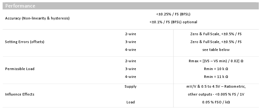
- Accuracy (Non-linearity & hysteresis)
- Thermal accuracy
- Electrical connection
- Process connection
- Process connection material
- O ring seal material
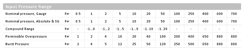
Pressure Ranges
Datum
- Absolute (A)
- Gauge (G)
- Sealed Gauge (S)
Range
- 1 bar (1000)
- 1.6 bar (1600)
- 2 bar (2000)
- 5 bar (5000)
- 10 bar (1002)
- 16 bar (1602)
- 20 bar (2002)
- 35 bar (3502)
- 50 bar (5002)
- 100 bar (1003)
- 200 bar (2003)
- 250 bar (2503)
- 400 bar (4003)
- 600 bar (6003)
- 700 bar (7003)
- 0 to -1 bar (P0M1)
- -1 to 0 bar (M1P0)
- -1 to +1 bar (M1P1)
- 150 psi (P150)
- 1500 psi (P1K5)
Output Signal & Supply voltage
- mV/V, 4-wire (1)
- 2mV/V, 4-wire (2)
- 10mV/V, 4-wire (3)
- 4 – 20mA, 2-wire (5)
- 0 – 5V, 3-wire (6)
- 0 – 10V, 3-wire (7)
- 1 – 5V, 3-wire (8)
- 0.5 – 4.5V, 3-wire ratiometric (9)
- 1 – 10V, 3-wire (A)
- 1 – 6V, 3-wire (B)
- 0 – 6V, 3-wire (C)
- 0.5 – 4.5V, 3-wire regulated (D)

Performance
Non-Linearity and Hysteresis
- 0.25% FS (standard) (A)
- 0.1% FS (B)
Thermal Zero Shift
- 0.04% FS per °C (standard) (4)
- 0.02% FS per °C (2)
- 0.01% FS per °C (1)
Permissible Temperatures & Thermal Effects
Media temperature
- -20°C to +135°C (150°C with integrated cooling element)
Ambient temperature
- -20° to +80°C
Storage temperature
- -40°C to +125°C
Compensated temperature range
- +20°C to +80°C
Thermal Zero Shift (TZS)
- <±0.04% / FS / °C (option code 4)
- <±0.02% / FS / °C (option code 2)
- <±0.01% / FS / °C (option code 1)
Thermal Span Shift (TSS)
- <-0.015% / °C
Electrical Protection
Supply reverse polarity protection
- No damage but also no function
Electromagnetic compatibility
- CE Compliant
Mechanical Stability
Shock
- 100 g / 11 ms
Vibration
- 10 g RMS (20 … 2000 Hz)
Materials
Housing & process connection
- 303 Stainless Steel
- 316L Stainless Steel (optional)
- High Grade DUPLEX Stainless Steel UNS31803 (optional)
- PVDF (optional)
‘O’ ring seals
- Viton (standard)(V)
- NBR (N)
- EPDM (E)
- FFKM (C)
Diaphragm
- Ceramic Al2O3 96 %
Media wetted parts
- Housing and process connection
- ‘O’ ring seal
- Diaphragm
Miscellaneous
Current consumption
- 2-wire – Limits at 25mA
- 3-wire – Typ. 6mA
- 4-wire Typ.2 – 5mA
Weight
- Approx. 100g
Installation position
- Any
Operation Life
- > 100 x 106 cycles
Insulation Resistance
- >500M O at 50V dc
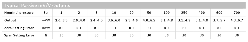
Typical Passive mV/V Outputs
Wiring Designation
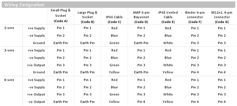
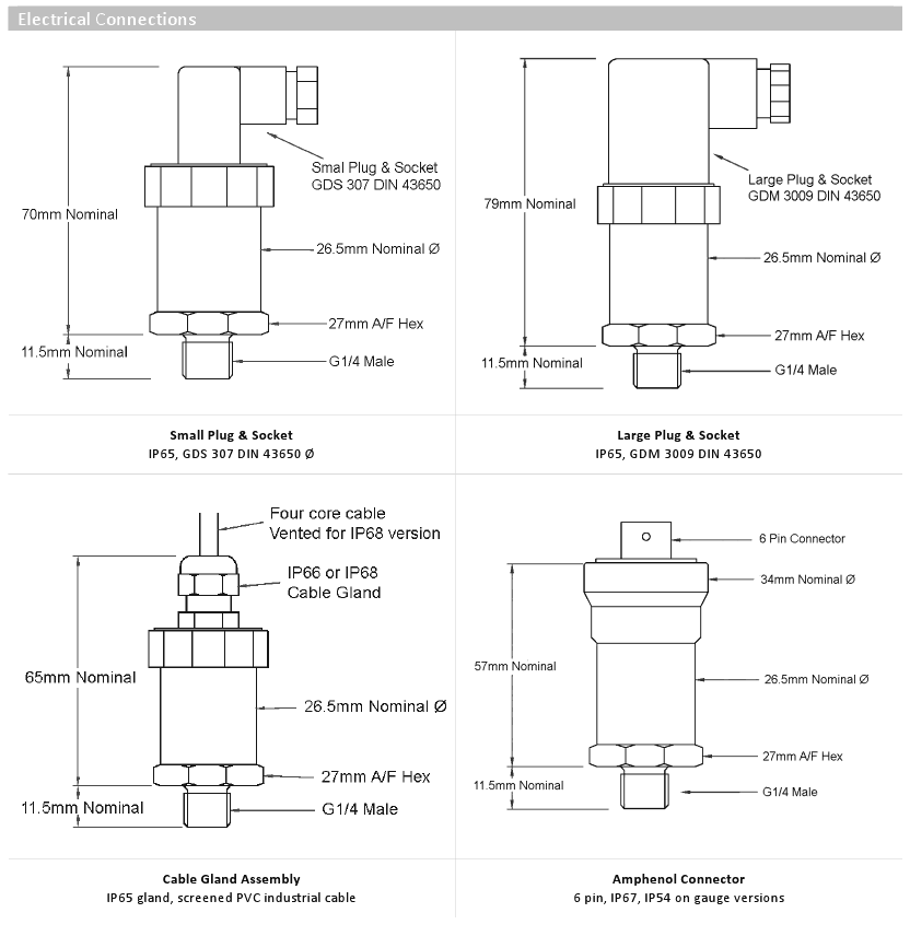
Electrical Connections
Connector Types
- Small DIN plug (A)
- Large DIN plug (B)
- IP66 cable gland (C)
- Military 6 Pin connector (D)
- IP68 cable gland (E)
- Binder 6 Pin connector (F)
- M12 4 pin connector (G)
- Other(specify in comments)
Cable Length
Any length of cable can be specified in metres for the cable gland versions. The vented cable is only available with the IP68 cable gland.
Any length of non-vented cable can also be fitted to the small and large mating DIN plug connectors.
Process Connections
- G1/4 male DIN 3852 (A)
- G 1/4 male DIN 3852, 316 St/St (B)
- 1/4 NPT male (C)
- 7/16 UNF – 20 (D)
- G1/4 female, 303 St/St (E)
- G1/2 male DIN 3852 (F)
- 1/2 NPT male (G)
- 9/16 UNF Internal Thread (H)
- G1/4 male, HG ST/ST (I)
- G1/4 male DIN 3852 with Snubber (J)
- G1/2 male DIN 3852 with Snubber (K)
- M20 x 1.5 male (L)
- G1/8 male DIN 3852 (M)
- 1/8 NPT male (N)
- G3/8 male DIN 3852 (O)
- G1/4 male, 150°C Integrated cooler (P)
- G1/2 male, 150°C Integrated cooler (Q)
- 1/4 NPT male, PVDF, 60 bar max, FFKM seal only (X)
Special Codes
The IMP pressure sensor was designed to be easily customised, and in addition to the standard options for electrical and mechanical configuration, the sensor can also be specially tailored to a particular OEM requirement and given a unique 3 digit part number code.
Part Number Structure
Part Number Builder
Generate or decode IMP ordering code
Related Documents
Specification data sheet
Product configuration
Request Product Price
Please select the options you require for the IMP Industrial Pressure Sensor in your application and request a quote.
"*" indicates required fields