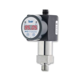
Three in one hydrostatic level switch, digital level gauge and level sensor with level ranges from 1 mWG up to 600 mWG (3.3 to 1969 ftWG).
Product Parameters
- Hydrostatic Level Ranges: 1 mWC up to 600 mWC (3.3 – 1969 ftWC)
- Accuracy: 0.35%Fs standard with option for 0.25%FS IEC60770 (analogue output)
- Output Signals: 4-20mA 2 wire, 0-10V 3 wire and Adjustable 4-20mA 3 wire
- Electrical Connections: Connections: DIN43650A plug & socket, cable gland, Binder 5 pin, M12 x 1 5-8 pin plastic or 5pin metal connector
- Pressure Connections: G1/2 and G1/4 DIN3852 or EN837, G1/2 and G3/4 DIN3852 flush, 1/2 and 1/4 NPT male
- Display: 4 digit red LED, 0.1% FS +/- 1 digit accuracy plus analogue output accuracy
- Switch Contacts: PNP, 125mA max for 4-20mA (2 or 3 wire) and 500mA max for 0-10V output.
- Environmental Protection: IP65
- Special Options: 5 to 1 rangeable, Ex approved intrinsic safety, all welded wetted parts
Product Description
The DS 200 combined hydrostatic level switch, gauge and sensor is externally powered via the analogue signal electrical connection and level can be displayed in any engineering units via the 4 digit LED display. A variety of analog output signals maybe specified and a choice of 1 or 2 PNP contacts for use as alarms or for controlling pumps and valves.
Special product features include a turndown ratio of 5 to 1 for the 3 wire 4-20mA output version for flexibility when stocking spares and an ATEX approved version of the 2 wire 4 to 20 mA output for hazardous area applications.
Product Help
Pressure wash skid
We are building a pressure wash skid. The specification calls for a pressure indicator with control switch (PICS). The operating pressure is 100 bar, the fluid is clean ambient water and will be installed in a safe area (not ATEX).
We would suggest a DS200 with the following specification for displaying the pressure reading and providing a continuous voltage output which can be switched on/off at a threshold pressure, and a 4-20mA current output for feeding into a PID controller.
- SKU ID: s1-ds200-0002
- Part No: 780-1002-1-1-3-100-100-1-000
- Pressure Range: 100
- Units: bar
- Range Type: Positive Gauge (atm to +P)
- Output Signal: 4-20mA (2 wire)
- Accuracy: 0.35%FS >= 0.4 bar, 0.5% < 0.4bar (11-12bit resolution)
- Switch Output: 1 PNP switch
- Electrical Connection: DIN plug (1 switch, 4-20mA 2 wire only)
- Process Connection: G1/2 DIN3852 male
- Process Connector Material: Stainless steel 316L
- Diaphragm Material: Stainless steel 316L
- Media Exposed Seals: FKM
Eliminating zero drift on compound ranges
At present we are using -1 to +1 bar compound pressure type pressure transducers with displays for use on our Crankcase Ventilation (CCV) test rig , but the devices are giving us problems, as the zero point appears to vary in compound range mode. The actual sensor ranges we need are -50 to +150mbar, -500 to +150mbar and -200 to +50mbar, all need to be as accurate as possible at 0 mbar, the media that this will be measuring is air, but there may be some engine oil present as well. Would the DS200 offer any improvement on what we already have?
The zero will drift on all types of diaphragm based pressure sensors, some are better than others, but none are perfect.
It is easy to tare this at regular intervals with a single positive or negative range, but it is not easy to do with a compound range because the span is affected also.
Also you are using an instrument with a much higher base range and scaling it down to the required range, this will also make the zero worse. e.g. a -1 to 1 bar instrument scaled to -30 to +150 mbar is going to have larger drift pro-rata, since zero drift is a function of diaphragm performance and not related to signal conditioning.
Since the DS200 can be manufactured with lower custom pressure ranges, it will be possible to reduce the zero drift by specifying the exact range you require, but you will not eliminate the zero problem altogether as previously explained.
For a perfect zero reading we would suggest splitting the compound range into 2 sensors if possible, so you can easily remove zero drift at regular intervals.
Mounting options
Is there any mounting capability for these sensors?
There is no mounting bracket, so the DS200 relies solely on the process connection for holding the sensor in place.
Supply voltage for no signal output version
If no signal output is required what supply is required to power the digital display of the DS200?
The no output signal version requires any supply between 15-36Vdc.
Supply voltage for 4-20mA signal output version
How much voltage is required to power the 4 to 20 milliamp output version?
The 4-20mA version will require any voltage between 13-36Vdc (15-28Vdc for ATEX IS approved version), excluding any other load included in the current loop.
Related Documents
Specification data sheet
Request Product Price
Please select the options you require for the DS200 Combined Hydrostatic Level Switch, Gauge and Sensor in your application and request a quote.
