
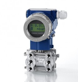
DP transmitter for measuring pressure difference between two pressure points which can tolerate up a very high overload pressure independently on either the positive or negative side port or both together at the same time.
The DPT 200 series is a highly accurate, versatile differential pressure transmitter engineered specifically for the stringent demands of the process industry. Capable of measuring differential pressures from 1 mbar up to 20 bar with a maximum static pressure rating of up to 400 bar, this instrument is exceptionally well-suited for level measurement in closed, pressurized tanks as well as the precise monitoring of pump and filter systems. Featuring standard HART® communication and an impressive maximum rangeability of 100:1, the DPT 200 series provides design and process engineers with unparalleled adaptability, robust performance, and reliable data acquisition even in highly demanding environments.
Product Parameters
- Differential pressure range: 1 mbar up to 20 bar
- Maximum static pressure: Up to 400 bar depending on the sensor type
- Output signal: 2-wire 4…20 mA with standard HART® communication
- Accuracy: 0.075 % FSO according to IEC 61298-2
- Rangeability (turn-down): Up to 100:1 with freely adjustable offset and span
- Supply voltage: 16.5…42 VDC for standard versions or 16.5…28 VDC for intrinsically safe versions
- Media temperature range: -40…+100 °C, with short term resistance up to +125 °C for a maximum of 30 minutes
- Ingress protection: IP 67
- Wetted parts: Stainless steel 1.4401 (316) process connection with a stainless steel 1.4435 (316L) diaphragm
Product Description
The DPT200 dp cell transmitter is a robust heavy duty pressure measurement instrument with a high and low pressure connection port to allow two pressure inputs. The DPT200 will measure the pressure difference between the Hi & Lo side and will output the result as a 2 wire 4 to 20 milliamp current loop signal.
Designed for maximum reliability and precision, the DPT 200 differential pressure transmitter utilizes advanced sensor technology to monitor the differential pressures of gases, steams, and liquids. The sensor architecture ensures stable measurements across a wide thermal and pressure spectrum. The output signal can be configured for either a linear or square root characteristic, allowing seamless integration into volume, flow, and level calculations natively within the instrument.
The device boasts a modular construction that permits extensive customization for unique application requirements. It can be equipped with various chemical pressure seals and diaphragm materials, guaranteeing optimal chemical compatibility and longevity when exposed to aggressive or high-temperature media. For operations requiring local readouts, an optional high-contrast, two-line LCD module is available, featuring an eight-digit numerical display and a 0…100% bargraph. This display module can be rotated in 90-degree steps for comfortable viewing at any installation angle.
Process configuration is straightforward and user-friendly. Adjustments to the measuring span, zero point, and damping, which is adjustable from 0.1…60 s, can be executed either locally via integrated push-buttons or remotely through the HART® communication protocol. This dual-access configuration minimizes downtime and simplifies calibration. For hazardous environments, the transmitter is available with strict explosion protection certifications, including ATEX intrinsically safe (Ex ia) and flameproof (Ex d) options, ensuring functional safety in critical gas and dust atmospheres.
Product Features
The DPT 200 series is engineered to provide superior performance and reliability in demanding industrial environments. Featuring a robust design with high overload resilience and exceptional measurement accuracy, this transmitter offers engineers a versatile and adaptable solution. With advanced connectivity options, flexible configuration settings, and compliance with strict safety standards, the DPT 200 ensures dependable process control and simplified maintenance across a wide range of critical applications.
One Sided Static Line Pressure Protection
Prevent unnecessary failures from accidental disconnection of process fittings or closing off isolation valves on one side of the dp level transmitter. The DPT200 has as standard built-in overload protection from unexpected high pressures on each port, whether applied to one side or both together.
Precision Measurement Accuracy
The DPT 200 ensures uncompromised reliability in critical processes, boasting an exceptional measurement accuracy with a deviation of only 0.075 % FSO. This high level of precision allows for consistent and dependable data acquisition across a wide range of industrial applications, ensuring that even the most subtle pressure changes are captured accurately.
High Overload Resilience
Built to withstand demanding process conditions, the transmitter features a high overload capability, with a maximum static overpressure limit reaching up to 400 bar. This robust construction provides security against pressure spikes and system surges, ensuring the integrity of the instrument and the safety of the surrounding infrastructure in high-pressure environments.
Versatile Rangeability
Experience unparalleled flexibility with the DPT 200’s dynamic scaling capabilities, which include a maximum rangeability (turn-down) of 100:1. This wide adjustability empowers engineers to configure the device for varied pressure spans while maintaining performance, reducing the need for multiple stock units and simplifying system design.
Seamless Connectivity
The device integrates standardized 2-wire 4…20 mA output with the widely recognized HART® communication protocol. This combination ensures seamless compatibility with existing process control architectures, enabling efficient data transmission, remote diagnostics, and simplified integration into complex industrial monitoring systems.
Configurable Output Characteristics
To accommodate diverse process requirements, the transmitter offers configurable output characteristics, supporting both linear and square root extraction options. This flexibility allows the DPT 200 to natively handle various volume, flow, and level calculations, providing direct and actionable process data without requiring secondary signal conditioning.
Wide Thermal Operational Range
Designed for challenging thermal environments, the DPT 200 supports a broad operational temperature range for media, spanning from -40 °C to +100 °C. This extensive thermal tolerance makes the transmitter suitable for a variety of process conditions, ensuring reliable performance in both cold-climate applications and high-temperature industrial processes.
Field-Adjustable Calibration
The DPT 200 simplifies maintenance and calibration through field-adjustable zero and span settings. By utilizing the accessible external push-buttons, operators can quickly and safely perform local adjustments without interrupting the process flow, minimizing potential downtime and improving operational efficiency.
Robust and Safe Housing Options
For deployment in hazardous or volatile locations, the transmitter supports a variety of optional specialized housings. These include ATEX-certified intrinsically safe (Ex ia) and flameproof (Ex d) configurations, which ensure operational safety in environments where flammable gases or combustible dust may be present, guaranteeing compliance with stringent safety regulations.
Product Applications
The DPT 200 series provides a versatile solution for differential pressure measurement, offering reliable and precise data acquisition across a diverse spectrum of industrial sectors. From optimizing filtration systems and monitoring pump networks to ensuring safety and efficiency in complex chemical processes and energy generation, the DPT 200 delivers consistent performance in demanding applications that require accurate differential pressure tracking.
Level Measurement in Pressurized Vessels
The DPT 200 is engineered for highly accurate level and volume tracking in closed, pressurized storage tanks. By measuring the hydrostatic differential pressure, calculating the variance between the pressure at the tank’s base and the internal gas-phase pressure above the liquid, the transmitter provides precise fill-level data. This method ensures reliable measurement regardless of the operating pressure or density fluctuations within the vessel.
Industrial Filtration Monitoring
To optimize maintenance schedules and prevent system strain, the DPT 200 monitors differential pressure across industrial filtration systems. By detecting the pressure drop between the inlet and outlet of a filter, the transmitter effectively identifies the point of fouling or clogging. This allows operators to perform timely maintenance, ensuring consistent flow efficiency and protecting downstream components from damage caused by debris or pressure build-up.
Fluid and Gas Pumping Network Monitoring
In critical pumping networks, the DPT 200 is used to determine flow velocity and verify pump performance. By measuring the differential pressure across a primary flow element, such as an orifice plate, venturi nozzle, or pitot tube, the transmitter provides essential feedback for flow calculations. This ensures that pumping operations remain within optimal curves, preventing cavitation and maintaining stable network output.
Oil and Gas Sector Processing
Within the high-stakes environment of oil and gas extraction and refining, the DPT 200 provides essential pressure diagnostics. It utilizes differential pressure measurement to monitor flow across separators, pipelines, and extraction manifolds. This enables operators to track critical operational variables under high-static pressure conditions, ensuring that both processing throughput and safety protocols are maintained.
Chemical and Petrochemical Process Control
The DPT 200 is designed for the rigorous demands of chemical process loops. By continuously measuring the differential pressure across reactor vessels, heat exchangers, and distillation columns, it allows for the precise regulation of chemical reactions and fluid distribution. This ensures consistent product quality and provides real-time data for control systems managing highly reactive or complex chemical compositions.
Energy Generation and Media Containment
In power generation facilities, the DPT 200 enables reliable pressure analysis for critical media containment. It monitors steam lines, cooling water circuits, and fuel delivery systems by accurately measuring the differential pressure across these loops. This continuous oversight is vital for maintaining the operational safety and efficiency of energy systems, ensuring that power output remains stable and infrastructure is protected.
Product Specifying Guide
Establish the required pressure ranges
Determine the nominal differential pressure span required for your application, ranging from 10 mbar up to 20 bar. Concurrently, identify the maximum static pressure your system will reach, ensuring it does not exceed the sensor’s limits, which can be specified up to 160 bar or 400 bar depending on the selected sensor type.
Select the output and explosion protection rating
Define the environmental safety classification of your installation zone. Select the standard 4…20 mA output for general-purpose areas, or specify the ATEX intrinsically safe (Ex ia) or flameproof (Ex d) configurations if the transmitter will be deployed in volatile gas or dust atmospheres.
Choose housing and display options
Evaluate the ambient conditions to choose between the standard die-cast aluminium housing with blue epoxy painting or the robust stainless steel 1.4404 (316L) option. Decide if a local readout is necessary; if so, specify the integration of the optional two-line LCD display with bargraph functionality.
Determine the process and electrical connections
Identify the mechanical interface required, typically a 1/4-18 NPT female thread, and select appropriate mounting bracket materials. For electrical integration, designate whether a standard terminal clamp with an M20x1.5 cable gland is sufficient or if specialized connections are needed to maintain your facility’s ingress protection standards.
Verify media compatibility
Analyze the chemical properties and temperature profile of the measured fluid or gas. Standard units feature a stainless steel 1.4435 (316L) diaphragm and silicone oil fill. For incompatible or highly specialized media, request alternative membrane materials or fill fluids, such as fluorolube oil, to prevent sensor degradation.
Part Number Builder
Generate or decode DPT 200 ordering code
Installation & Operation Guide
Inspect and prepare the installation site
Carefully remove the transmitter from its packaging, retaining any protective caps on the diaphragms until immediately before mounting. Verify that the sealing surfaces on the process connections are perfectly smooth, clean, and compatible with the media. Ensure the installation location provides adequate drainage for condensation and protects the device from direct, excessive sunlight.
Mount the transmitter securely
For NPT connections, suitable sealing tape may be utilized. Hand-thread the device into the pressure port, then tighten using an open-end wrench. Observe the maximum tightening torques, which is approximately 30 Nm for 1/4 NPT, to avoid mechanical stress that could shift the calibration characteristic.
Connect the pressure lines
Connect the higher system pressure to the input marked with a plus sign and the lower system pressure to the input marked with a minus sign. In hydraulic applications, orient the device so the pressure connectors face upwards to facilitate natural venting. If installing the transmitter in steam lines, incorporate an adequate cooling section to protect the sensor from extreme temperatures.
Establish the electrical wiring
Unscrew the housing cover to access the terminal block. If an LCD module is present, carefully unplug it to avoid straining the connections. Connect the shielded, twisted multicore cable to the appropriate supply plus and supply minus terminals. Once wired, inspect the housing O-rings for damage, carefully reconnect the display module, and hand-tighten the cover to re-establish the tight seal.
Configure the operating parameters
Power the system within the 16.5…42 VDC range or the specified intrinsic safety limits. Adjust the zero point and measuring span using either a HART® communicator or the integrated Z and S push-buttons. To execute a zero-point trim physically, apply the reference zero pressure and simultaneously hold the Z and S buttons for 2 to 5 seconds until the display confirms the update.
Product Help
Operating principle of the output signal
How do I change the output signal from linear to square root?
The output signal characteristic can be toggled between linear and square root extraction depending on your process requirements. This configuration is accessible via the device’s internal menu under the function setting or can be programmed remotely using a standard HART® communicator.
Display module orientation
Can the integrated display be rotated for easier reading after installation?
Yes, the optional LCD display module is designed for versatile readability. It can be physically rotated in 90-degree steps. This allows the operator to orient the numerical readout and bargraph upright regardless of how the transmitter is mounted to the pipe or vessel.
Zero point recalibration
How do I reset the zero point if the transmitter experiences a slight drift over time?
If a minor signal deviation occurs after prolonged use, you can execute a zero-point trim. Depressurize the system to establish a true zero reference, then press and hold the Z and S buttons simultaneously for 2 to 5 seconds. The analog output will reset to 4 mA, and “OK” will appear on the display if the procedure is successful.
Flow rate calculation using square root extraction
How does the square root extraction function in a differential pressure transmitter facilitate flow measurement in a 2-wire control loop?
In many industrial applications, flow rate is determined by measuring the differential pressure (ΔP) across a primary flow element, such as an orifice plate, Venturi tube, or Pitot tube. According to Bernoulli’s principle, the flow rate is proportional to the square root of the differential pressure. Without internal processing, a transmitter would output a signal linear to the pressure, requiring the PLC or DCS to perform the complex calculation.
The DPT 200 series features an integrated square root extraction function that can be enabled locally via the menu-driven display. When activated, the transmitter internally calculates the square root of the measured ΔP and adjusts the 4-20 mA output signal to be linear to the flow rate rather than the pressure. This allows for direct integration into simpler monitoring systems that may lack advanced math capabilities. This is particularly useful in HVAC systems for measuring air volume in ducts (CFM) or in process plants for liquid flow (USGPM).
Diaphragm protection against one-sided overload conditions
How does a differential pressure transmitter protect the sensing diaphragm from damage during accidental one-sided pressure spikes or the improper sequence of isolation valve operation?
In many differential pressure applications, such as level measurement in pressurized tanks or flow lines, the instrument is exposed to high static line pressure on both ports. A common risk occurs during commissioning or maintenance if an isolation valve is opened or closed in the wrong order, applying the full line pressure to only one side of the diaphragm.
To prevent catastrophic failure, the DPT 200 is engineered with robust one-sided overload protection. The internal sensing cell is designed to withstand the maximum rated static pressure—up to 160 bar or even 400 bar depending on the version—on either the high (+) or low (-) port independently. This mechanical protection prevents the diaphragm from over-stretching or rupturing, ensuring the instrument returns to its calibrated accuracy once the differential pressure returns to normal operating ranges.
Process connection standards for manifold mounting
Why is a 7/16-24 UNF fixing pattern necessary for 1/4-18 NPT process connections in North American industrial manifold installations?
In the United States and North American markets, differential pressure transmitters are frequently mounted directly to 3-valve or 5-valve manifolds to allow for easier calibration and maintenance without breaking the process seals. The industry standard for these manifolds utilizes 1/4″ NPT female ports for the process media, but the physical attachment of the transmitter to the manifold requires a specific bolt pattern.
The “N20” configuration for instruments like the DPT 200 provides the 1/4-18 NPT internal thread along with a 7/16-24 UNF fixing pattern. This specific bolt spacing and thread type ensures mechanical compatibility with standard industrial manifolds and mounting brackets used in oil, gas, and chemical processing. This standardization allows technicians to use common tools and hardware for installation, reducing the risk of leaks and ensuring a secure, vibration-resistant connection in harsh industrial environments.
Calculating thermal error with a turndown ratio
For an adjustable differential pressure transmitter like the DPT200 series, how is the temperature error calculated when the instrument is ranged down from its maximum range, for instance, when operating at 80°C?
The temperature error for a smart or adjustable transmitter is not a fixed percentage of reading. It is typically dependent on the turndown ratio (TDR) and the specific operating temperature band. The datasheet provides formulas to calculate this error.
First, determine the Turndown Ratio (TDR). This is the ratio of the transmitter’s maximum possible range (its Upper Range Limit or URL) to the specific range you have configured it for (the Adjusted Span).
TDR = Maximum Range (URL) / Adjusted Span
For the DPT200 series with a 0-60 mbar maximum range, the TDR would be:
TDR = 60 mbar / Adjusted Span in mbar
Next, consult the product datasheet for the thermal effect specification. This is often broken down into different temperature bands. For the DPT200, the temperature range is split into three bands, with a specific formula for the +65°C to +100°C band.
For a media temperature of 80°C, the error calculation is:
Thermal Error (mbar) = ±(((0.30 × TDR) + 0.2) / 100) × Adjusted Span (mbar)
Explanation of the Formula:
±: The calculated maximum temperature error is directional and should be applied in both directions in reference ot the readings.- 0.30 x TDR: This term shows that part of the error is proportional to the turndown. As you turn the sensor down (i.e., use a smaller portion of its maximum range), the TDR increases, and this component of the error becomes larger.
- +
0.2: This is a fixed base error component that is independent of the turndown. / 100: This converts the combined error factors into a percentage.x Adjusted Span: This applies the calculated percentage error to your specific configured range to find the potential error in engineering units (mbar).
It is crucial to use the formula corresponding to the correct operating temperature band, as the sensor’s thermal performance is not linear across its entire range.
Measure filter dp to 20mbar & withstand 1bar cleaning pulse
I am looking to measure a differential pressure across a filter element. Air is being drawn through the filter via an extraction fan so that downstream of the filter the pressure is -1000Pa. As the filter becomes coated with dust the differential pressure across it will rise from 5mbar to 10mbar, at this point we wish to send a signal to a control panel. The control panel will send a pulse of gas up to 1 bar to clean the element and the procedure will begin again. A 20mbar dp with a 1 bar overpressure rating would be ideal.
The DPT200 has very good overpressure rating on either port and it is possible to scale the output to read over 0-20 mbar. The accuracy will be 0.1% of 20 mbar = 0.03 mbar. You can use a positive differential range to measure a suction range by connecting the positive port to the upstream side of the filter and the negative port to the downstream side of the filter.
- SKU ID: s1-dpt200-0004
- Part No: 343-C-1-H-17-L-AL-AK0-N20-0-N20-0-12-11-1-000
- Pressure Datum: Differential Pressure
- Differential Pressure Range: 0 ‐ 4 mbar up to 0 ‐ 400 mbar
- Factory Set Range: 0 to 20 mbar
- Maximum Static Pressure: 160 bar
- Display: With backlit display
- Output: 4-20mA/ 2-wire with HART
- Accuracy: <±0.075% / FSO IEC 60770
- Electrical Connection: Terminal clamp / M20 x 1.5 Cable Gland
- Housing Material: Aluminium
- Process Connection: Internal thread 1/4″‐18 NPT
- Process Connection Material: Stainless Steel 1.4401 (316)
- Diaphragm Material: Stainless Steel 1.4435 (316L)
- Seal Material: FKM
- Special Options: None
- Supply Voltage: 12 ‐ 42 V dc
- IP Rating: 67
- Media Temperature: -40 to +100°C
- Operating Temperature: -20 to +65°C
- Approvals: None
1/2NPTF with adapter and 1/4-18 NPTF/fixing 7/16 UNF meaning
For the process connection code the N57 – 1/2″ NPT F with adapter and also the N20 – 1/4″-18 NPT F/ fixing 7/16 UNF. What does this mean?
For the code N20, this refers to a base process connection of 1/4″-NPT internal thread, and then the fixing holes used to mount the sensor, which in this case are 7/16″ UNF internal thread.
For the code N57, this refers to 1/2″ NPT F thread oval shaped adapter for the high and low side process connections, which is screwed onto the standard 1/4 NPT internal thread flange assembly using the fixing holes and elastomer seals.
Fixing holes thread size with oval adapters
What is the fixing hole thread for the 1/2″ NPT F with adapter process connector option? It is not mentioned on the data sheet, but the other process connection options specify the fixing hole thread.
The 4 fixing holes on each side of the DP sensor used for mounting brackets, valve blocks and oval adapters are 7/16” UNF with the 1/2 NPT oval adapter opton, but these will not be available since they are used to fit the oval adapters to the dp sensor.
Top vs Bottom side valves
For the valve on the H-side and L-side, what does having a vent on the top and the bottom mean, and also does having a vent mean we would be able to bleed the system with air it has the “with vent” option?
The top side means the valve is fitted to upper most fitting on the process connection flange assembly which is ideally located for bleeding off trapped air.
The bottom side means the valve is fitted to the low most fitting on the process connection flange assembly which is ideally located for draining fluid.
Accuracy of -10 to +10 mbar range
For the DPT 200 Type A version with setting measurement span of -10 to +10mbar, is the accuracy 0.075% of 20mbar i.e. 1.5Pa?
Yes the accuracy is 0.075% of FSO full scale output. -10 to +10 mbar reflects the operating range of the 4-20mA output signal, therefore the negative and positive ranges are combined together to determine the full scale, which in this case is 20 mbar.
H-side & L-side valves
What does “Valve H-side” and “Value L-side” mean?
There valves are optional accessories to allow the user to vent air, or drain process fluids on both process connections of this differential pressure transmitter. H-side means the high or positive pressure port, and L-side means the low or negative pressure port.
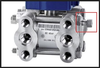
Over-pressure limit
What is the over-pressure limit on the Hi & Lo pressure side?
This differential pressure transmitter is designed to withstand the maximum line pressure on one side only, irrespective of whether it is applied to the Hi or Lo pressure side process connections.
Related Documents
Specification data sheet
Request Product Price
"*" indicates required fields