
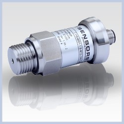
The DCT 531 is an industrial pressure transmitter featuring a high-quality stainless steel sensor and a digital RS485 interface utilizing the open Modbus RTU communication protocol.
Designed to meet the demanding requirements of plant engineering, machine engineering, and the energy industry, this device provides exceptional reliability with an accuracy of 0.25% FSO according to IEC 61298-2. It accommodates a wide span of nominal pressures extending from 0 to 100 mbar up to 0 to 400 bar, ensuring versatile configuration options for relative or absolute pressure measurements across diverse on-site conditions. Constructed with robust 316L stainless steel wetted parts and offering an array of customizable mechanical connections, the transmitter delivers excellent thermal behaviour, low long-term stability drift, and permanent electrical protections within an IP67-rated enclosure.
Product Parameters
- Pressure Range: 0 to 100 mbar up to 0 to 400 bar gauge or absolute.
- Output signal: RS485 communications with Modbus RTU protocol.
- Accuracy: 0.25% full scale output IEC 61298-2 limit point standardizations.
- Materials: Stainless steel 1.4404 (316L) housing and process port combined with a stainless steel 1.4435 (316L) isolation diaphragm.
- Elastomeric Seals: FKM, EPDM or all welded.
- Supply voltage: 9 to 32 Vdc.
- Electrical Connections: M12 x 1 5 pin metal connector (IP67)
- Pressure Connections: 1/4 BSP male DIN3852 or EN837, 1/2 BSP male DIN3852, EN837, flush or open port, 1/4 NPT male, 1/2 NPT male
- Ingress protection: IP67
Product Description
The DCT 531 industrial pressure transmitter represents a highly adaptable digital measurement solution designed for integration into contemporary automation and control topologies. By implementing the open Modbus RTU protocol over a physical RS485 serial bus, the device supports robust master-slave networking arrangements where a single master controller can interface with up to 247 distinct slave nodes. This digital communication format eliminates analog transmission loop errors and allows direct acquisition of high-precision pressure data alongside internal telemetry variables such as device status and system temperatures. The transmitter features a high sampling measurement rate of 500 Hz paired with a fast delay time of 500 msec, allowing for dynamic process monitoring in high-throughput industrial network installations.
Engineered to operate under severe mechanical and environmental stresses, the mechanical architecture of the device relies entirely on premium metallurgical selections. The external housing and process port are milled from stainless steel 1.4404 (316L), while the internal sensing diaphragm is fabricated from stainless steel 1.4435 (316L), ensuring superior chemical compatibility with a broad array of industrial gases and liquids. Mechanical stability is validated by high vibration resistance up to 20 g RMS across a frequency range of 10 to 2000 Hz, and shock resistance rated at 500 g for a 1 msec half-sine duration. For specialized process requirements, optional configurations include a fully welded sensor assembly suitable for process pressures up to 40 bar, which eliminates internal elastomeric seals entirely to minimize failure points.
The digital infrastructure of the transmitter incorporates several internal registers that facilitate field configuration of data processing parameters. Through holding register adjustments, engineers can modify the device slave network address, select baud rates from 4800 up to 38400 baud, change parity settings, and adjust engineering measurement units across standard scales including bar, mbar, psi, and Pascals. To guard against operational anomalies, permanent short-circuit protection is integrated alongside comprehensive electromagnetic compatibility matching emission and immunity criteria set under EN 61326 compliance mandates. Furthermore, an integrated auxiliary hardware line allows an field technician to trigger a complete service reset to original factory defaults by applying a simultaneous 24 V potential to the designated reset pin during power-up.
Product Features
The DCT 531 is engineered for versatility and reliability, offering advanced digital communication via Modbus RTU, high-speed dynamic process monitoring, and robust diagnostic capabilities. Its robust construction and compliant design ensure precision and safety across a wide range of industrial, municipal, and hygienic applications.
Open Industrial Communication
Utilizing the open Modbus RTU protocol over a physical RS485 serial bus, the transmitter supports complex multi-drop network architectures. This configuration allows for robust master-slave networking where a single controller can interface with up to 247 distinct slave nodes over long distances. The digital nature of this communication eliminates the signal degradation associated with traditional analog transmission loops, providing a scalable and cost-effective solution for distributed industrial monitoring.
Integrated Diagnostics
A dedicated integrated diagnostic and service reset function allows field technicians to quickly restore baseline factory parameters. By applying a 24 V potential to the designated reset pin during power-up, all internal holding registers—including the Modbus address and baud rate—are automatically overwritten to original defaults. This hardware-level override simplifies troubleshooting and recovery in scenarios where network communication settings have been lost or incorrectly configured.
Dynamic Process Monitoring
For high-throughput industrial environments, the transmitter features a high sampling measurement rate of up to 500 Hz paired with a fast delay time. This capability supports dynamic process monitoring, allowing the control system to capture rapid pressure fluctuations with high temporal resolution. Such performance is critical for applications in hydraulics and fluid power tracking where instantaneous data acquisition is necessary for safety and process optimization.
Hygienic & Drinking Water Compliance
The DCT 531 offers optional EPDM seal configurations that are fully compliant with DVGW W 270 and UBA KTW criteria. These certifications are essential for integration into municipal drinking water distribution and processing systems, ensuring that all materials meet strict hygienic and chemical safety standards. This flexibility allows the industrial transmitter to be adapted for specialized applications requiring high levels of environmental and biological compatibility.
Product Applications
The DCT 531 is designed to support a broad spectrum of industrial, energy, and municipal applications, leveraging its robust digital communication and high-speed data acquisition capabilities to ensure reliable performance across complex process monitoring and control environments.
Plant and Machinery Engineering
The DCT 531 is optimized for integration into complex plant and machinery engineering systems that manage various liquid or gaseous fluid process lines. Its robust 316L stainless steel construction ensures long-term durability and resistance to corrosive industrial media. By utilizing the Modbus RTU interface, machinery designers can seamlessly monitor pressure variables across the entire production floor without the noise interference typically associated with legacy analog signaling, ensuring stable and predictable equipment performance.
Energy Industry Infrastructure
Within energy industry infrastructures, the demand for remote digital monitoring of distributed piping arrays is met by the transmitter’s RS485 serial communication capabilities. The ability to network multiple devices over long distances using the open Modbus RTU protocol allows for centralized telemetry of pressure and temperature data. This digital transparency is vital for maintaining the structural integrity and operational efficiency of energy transport networks while minimizing the need for manual on-site inspections.
Municipal Drinking Water Supply
For municipal drinking water supply systems, the DCT 531 provides a compliant and hygienic solution. When configured with optional EPDM seals, the transmitter meets strict chemical and hygienic certifications such as DVGW W 270 and UBA KTW. Its stainless steel 1.4435 (316L) isolation diaphragm protects the purity of the water supply while providing the precision needed for leak detection and flow management within municipal distribution networks.
Dynamic Industrial Process Monitoring
High-speed industrial processes require the exceptional temporal resolution provided by the DCT 531’s 500 Hz sampling rate. This high-speed data acquisition allows for the tracking of rapid pressure fluctuations and transient events that slower transmitters might miss. Paired with a fast delay time, it serves as a critical component in dynamic monitoring environments where process safety and optimization depend on instantaneous feedback and high-fidelity data collection.
Multi-Node Automated Instrument Bus Configurations
The transmitter is purpose-built for multi-node automated instrument bus configurations, supporting up to 247 distinct slave devices on a single Modbus RTU network. This scalability allows engineers to build extensive sensor arrays with minimal wiring complexity. The integrated diagnostics and hardware reset function ensure that even in large-scale deployments, individual nodes can be easily managed, addressed, and restored to factory defaults during system commissioning or troubleshooting.
Hydraulic and Fluid Power Tracking
In hydraulic and fluid power tracking installations, the DCT 531 excels despite exposure to severe mechanical shock and high operational vibration profiles. Rated for vibration resistance up to 20 g RMS, the device maintains its 0.25% FSO accuracy even in the most punishing mechanical environments. This ruggedness, combined with its high-speed digital output, makes it an ideal choice for monitoring heavy-duty hydraulic actuators and fluid power systems where reliability is paramount.
Product Specifying Guide
Step 1: Determine nominal pressure range and measurement type
The application operating pressure determines both the sensor span and whether gauge or absolute pressure tracking is necessary. For low-pressure industrial environments, specify low-span options beginning at 100 mbar gauge, whereas heavy industrial processes can require scales reaching up to 400 bar. Ensure that the maximum overpressure limits of the selected range are fully matched to the highest potential system pressure spikes to prevent structural degradation of the internal stainless steel diaphragm.
Step 2: Select the required accuracy tier
Review the process control tolerance parameters to establish the appropriate performance level. The standard configuration delivers a calibrated accuracy of 0.25% FSO following the limit point adjustment method of IEC 61298-2. For critical control loops or high-precision research testing, consult configuration rules to determine the availability of specialized ultra-high accuracy variations down to 0.1% FSO.
Step 3: Choose mechanical process connection interface
The physical adaptation of the transmitter must align perfectly with existing piping or vessel architectures. Standard process connection offerings include threaded interfaces such as G1/4″ and G1/2″ conforming to DIN 3852 or EN 837 standards, alongside industrial NPT male connection options like 1/4″ NPT and 1/2″ NPT. If the system handles high-viscosity media or requires a minimized dead-space configuration, specify the open port G1/2″ semi-flush sensor version certified for pressures up to 40 bar.
Step 4: Verify elastomeric sealing material compatibility
Evaluate the chemical composition and temperature profile of the process medium to choose an appropriate sealing element. The transmitter comes equipped with an FKM seal as standard, making it compatible with a wide assortment of industrial hydrocarbons and gases. For applications involving drinking water or where specific hygienic certifications are required, specify an EPDM seal layout to ensure compliance with relevant DVGW W 270 and UBA KTW regulatory approvals.
Step 5: Select appropriate special options or certifications
Review any overarching system regulatory mandates that govern the operating space. If the pressure sensor is meant for building into water processing machinery, ensure that the order explicitly includes the necessary drinking water certificate designation. Similarly, if the equipment must operate under strict safe power constraints in North American regions, select configurations that meet UL approval parameters for indoor usage via an NEC Class 2 limited energy supply.
Part Number Builder
Generate or decode DCT 531 ordering code
Installation & Operation Guide
Step 1: Pre-installation visual inspection and safety verification
Before initiating mechanical mounting, verify that the device ordering code on the permanent manufacturing label corresponds exactly to system design specifications. Keep all protective shipping caps over the process threads and the sensitive exposed diaphragm intact until immediately prior to insertion. Ensure that the target measurement node is entirely depressurized and isolated from active electrical power loops to prevent injuries from pressurized fluid escape or electrical shock.
Step 2: Mechanical mounting and torque application
Thread the pressure transmitter into the mating process port by hand to avoid cross-threading. For mechanical connections styled after DIN 3852, check that the pre-fitted elastomeric O-ring is properly seated and completely free from physical scoring. Complete the tightening sequence by applying an open-end wrench to the integrated spanner flats, adhering to recommended maximum torque limits such as 10 Nm for steel G1/2″ DIN 3852 ports or 50 Nm for steel G1/2″ EN 837 connections.
Step 3: Electrical wiring and loop connection
Utilize a high-quality shielded and twisted multicore cable to establish electrical connections with the control system. Wire the transmitter using the standard M12x1 5-pin metal circular connector according to the designated pin configuration schema. Connect Pin 1 to the positive power supply line (9 to 32 VDC) and Pin 3 to the negative supply return line. Route the RS485 serial communication bus by wiring the non-inverted digital line A(+) to Pin 2 and the inverted digital line B(–) to Pin 4, while ensuring the plug housing is securely connected to the system shield.
Step 4: Bus initialization and protocol configuration
On first powering up the network loop, incorporate a mandatory initialization delay of 500 milliseconds to allow internal electronics to stabilize before transmitting digital command sequences. The instrument defaults to factory communication baselines consisting of Modbus address 1, a baud rate of 9600 baud, and even parity checking. Use a Modbus master system configuration tool to query input register map locations, such as register 0x0000 for serial tracking and register 0x0007 to read actual system pressure values.
Step 5: Implementing factory default reset sequence
If the assigned bus address is lost or network communications stall due to configuration errors, implement the auxiliary service reset procedure. Isolate the unit from power, then bridge the Pin 5 hardware reset line directly onto the positive 24 VDC supply voltage input. Apply power to the system simultaneously with this connection, allowing the internal microprocessor to recognize the hardware voltage override and automatically overwrite all holding registers back to original factory defaults. Disconnect the reset line promptly after initialization to return the unit to standard bus operating states.
Product Help
Protocol compatibility for the pressure transmitter
How can the transmitter be integrated into an existing industrial digital communication network?
The pressure transmitter features a standard RS485 serial interface and communicates natively using the open Modbus RTU protocol. This allows it to function as a slave device within a master-slave network architecture, where up to 247 unique transmitters can be individually addressed and polled by a central Modbus master controller.
Materials used in wetted components
Which materials are used in the construction of components that come into direct contact with the process media?
To ensure extensive chemical compatibility, the pressure port and external housing are manufactured from robust stainless steel 1.4404 (316L). The internal isolating measurement diaphragm is crafted from stainless steel 1.4435 (316L), and elastomeric sealing choices include standard high-grade FKM or optional process-matched EPDM configurations.
Procedure for factory address reset
What steps should be taken if the digital bus address is lost and the transmitter becomes unresponsive on the network?
The device includes a dedicated physical hardware reset pin on its M12x1 5-pin electrical connector to restore factory settings. By connecting this reset input pin to a 24 V potential simultaneously with the positive power supply input during start-up, the internal configuration registers are automatically overwritten back to factory defaults, restoring the slave address to 1 and the baud rate to 9600.
Requirements for drinking water usage
Is this industrial pressure transmitter suitable for integration into municipal drinking water distribution applications?
Environmental adaptation allows the transmitter to be explicitly configured for municipal drinking water systems by selecting the optional EPDM seal configuration. This variant is officially certified under European drinking water hygiene testing frameworks, confirming compliance for use within active drinking water installations.
Calibration shift from mounting positions
Will installing the pressure transmitter in a horizontal orientation affect its measurement accuracy?
The instrument is calibrated at the factory in a vertical position with the pressure connection pointing downward. If the installation orientation is changed on-site, a minor zero-point offset shift may occur due to gravity acting on the internal components, particularly in sensitive low-pressure ranges equal to or below 1 bar.
DCT 531i vs DCT 531
What is the difference between the DCT531i and the DCT531?
The DCT531i has improved temperature errors from active compensation, 0.1% accuracy as standard, 15 bit reading resolution, and provides measurement readings for both pressure and temperature via the digital interface.
Detecting 0.0006 bar change around 0.3 bar
We have an operational pressure of 0.3 bar, and we want to detect a pressure change of 0.006 bar, so ideally we want at least 4 decimal places resolution?
The 0.1% accuracy version of the DCT 531 has a 13 bit output resolution, so you should be able to detect in the order of 0.012% full scale. For a pressure range of 0.4 bar range this would be equivalent to 0.000048 bar, which would comfortably exceed your resolution requirements.
Temperature measurement
Is it possible to also measure temperature with the DCT 531?
Yes it is, but not as standard, to measure pressure and temperature you would need a version called the DCT 531i. This comes with an extra set of Modbus RTU input registers, holding registers, and enumeration for reading temperature and selecting temperature units
Custom Modbus configuration
Is it possible to request custom Modbus settings for address and other settings?
Yes a specific Modbus settings can be configured by the factory if specified when ordered.
High vacuum resistance
What does the vacuum resistance spec of unlimited vacuum resistance for pressure greater than 1 bar mean?
This refers to high vacuum resistance only, so it is not advisable to expose ranges below 1 bar to a high vacuum since this likely to alter the performance of the sensor, and ranges of 1 bar or greater are not affected by exposure to a high vacuum.
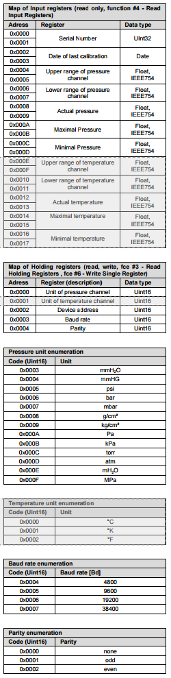
Modbus RTU register values
What are the register values for sending commands to the Modbus RTU communications?
The explicit register description is shown in the table below:
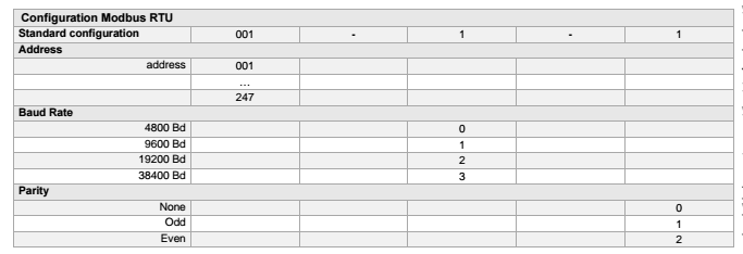
Modbus RTU configuration
I’d like to check the compatibility of the Modbus connection and would appreciate if you could show the configuration documentation, in particular I’m interested in the facilities for changing network id, baud rate and parity?
Click on the image below to view the Modbus RTU configuration for the BD Sensors DCT 531:
Irrigation water control
We are looking for a 2-wire pressure transducer in the 0-30psig range with a Modbus RS485 output. Our industry is irrigation water control.
We would suggest the following DCT531 specification:
- SKU ID: s1-dct531-0002
- Part No: DC7-2501-L5-2-N11-N00-1-000
- Pressure Range: 0 – 2.5 bar g
- Output: RS 485
- Supply Voltage: 9 – 32V dc
- Electrical Connection: Male plug M12x1 (5-pin) / metal
- Process Connection: 1/2 NPT male
- Process Connection Material: Stainless Steel 316L
- Seal Material: FKM
- Diaphragm Material: Stainless Steel 316L
- Accuracy (NL&H): 0.25% FSO IEC 60770
- IP Rating: 65
- Media Temperature: -25 to +125°C
- Operating Temperature: -25 to +85°C
- Special Options: None
- Approvals: None
10 bar range with cable connection
We need a sensor to measure up to 10 bar on air for a development project. We have a system capable of using a Modbus RTU serial interface for transmitting the data. A 12v supply is available and we would need a direct cable connection to the probe?
The following spec would meet all your requirements.
- SKU ID: s1-dct531-0001
- Part No: DC7-1002-L5-2-N11-100-1-000
- Pressure Range: 0 – 10 Bar G
- Output: RS 485
- Supply Voltage: 9 – 32V dc
- Electrical Connection: Male plug M12x1 (5-pin) / metal
- Process Connection: G 1/2″ DIN 3852
- Process Connection Material: Stainless Steel 316L
- Seal Material: FKM
- Diaphragm Material: Stainless Steel 316L
- Accuracy (NL&H): 0.25% FSO IEC 60770
- IP Rating: 65
- Media Temperature: -25 to +125°C
- Operating Temperature: -25 to +85°C
- Special Options: None
- Approvals: None
Part Numbers
DC8-1002-L5-3-TA0-N40-1-000
10 bar absolute range Modbus RTU pressure sensor for installing with a 1/4 NPT male pressure fitting and a 2 metre length of cable.
- SKU ID: s1-dct531-0005
- Part No: DC8-1002-L5-2-N11-N40-1-000
- Pressure Range: 0 – 10 bar absolute
- Output: RS 485 Modbus RTU
- Supply Voltage: 9 – 32V dc
- Electrical Connection: Male plug M12x1 (5-pin)
- Process Connection: 1/4 NPT male
- Process Connection Material: Stainless Steel 316L
- Seal Material: FKM
- Diaphragm Material: Stainless Steel 316L
- Accuracy (NL&H): 0.25% FSO IEC 60770
- IP Rating: 65
- Media Temperature: -25 to +125°C
- Operating Temperature: -25 to +85°C
- Special Options: None
- Approvals: None
DC7-1602-L5-3-M13-300-1-000
16 bar gauge RS485 Modbus RTU digital interface pressure sensor.
- SKU ID: s1-dct531-0003
- Part No: DC7-1602-L5-2-N11-300-1-000
- Pressure Range: 0 – 16 Bar G
- Output: RS 485
- Supply Voltage: 9 – 32V dc
- Electrical Connection: Male plug M12x1 (5-pin) / metal (excludes mating connector)
- Process Connection: G1/4 DIN 3852 male
- Process Connection Material: Stainless Steel 316L
- Seal Material: FKM
- Diaphragm Material: Stainless Steel 316L
- Accuracy (NL&H): 0.25% FSO IEC 60770
- IP Rating: 65
- Media Temperature: -25 to +125°C
- Operating Temperature: -25 to +85°C
- Special Options: None
- Approvals: None
DC7-4002-L5-3-M13-300-1-000
40 bar gauge RS485 Modbus RTU digital interface pressure sensor.
- SKU ID: s1-dct531-0004
- Part No: DC7-4002-L5-2-N11-300-1-000
- Pressure Range: 0 – 40 Bar G
- Output: RS 485
- Supply Voltage: 9 – 32V dc
- Electrical Connection: Male plug M12x1 (5-pin) / metal (excludes mating connector)
- Process Connection: G1/4 DIN 3852 male
- Process Connection Material: Stainless Steel 316L
- Seal Material: FKM
- Diaphragm Material: Stainless Steel 316L
- Accuracy (NL&H): 0.25% FSO IEC 60770
- IP Rating: 65
- Media Temperature: -25 to +125°C
- Operating Temperature: -25 to +85°C
- Special Options: None
- Approvals: None
Related Documents
Specification data sheet
Request Product Price
"*" indicates required fields