| Select Answer Mode | |
|---|---|
| Supply & Load Values | |
| Min / Max Limits | |
| Shunt Signal Values | |
Click save settings to reload page with unique web page address for bookmarking and sharing the current tool settings
Related Tools
- 4-20mA Signal to Measurement Reading Converter
- DP Flow Transmitter Output Calculator
- Flow Transmitter 4-20mA Current Output Calculator
- Liquid Level Transmitter 4-20mA Current Output Calculator
- Pressure Transmitter 4-20mA Current Output Calculator
- SqRt Extraction 4-20mA Signal to Measurement Reading Converter
- Temperature Transmitter 4-20mA Current Output Calculator
User Guide
 This 4-20mA current loop signal circuit tool will calculate all the electrical parameters associated with the power supply, load resistance, transmitter supply, shunt voltage drop and current signal.
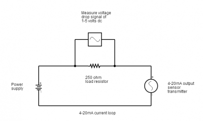
Since all the components in a 4 to 20mA circuit are connected together in series to form a loop circuit, and the current in the loop is regulated by the transmitter, any change to the electrical characteristics of one component will have a direct effect on the electrical parameters of the other components.
Answer Modes
Supply & Load Values
These parameters will help you determine how supply voltages are effected by changes in load resistance and current output signal.
Min / Max Limits
These answer modes will provide you with the required limits of operation for minimum supply voltage and maximum load resistance, so you can select a suitable transmitter, load resistor or power supply.
Shunt Signal Values
When a shunt resistor (load) is placed in series with the transmitter and power supply, it will cause a voltage drop across it, the level of voltage drop is directly related to the current flowing through it and the shunt resistance. This is how measuring instrumentation converts a 4-20mA signal, by placing a shunt resistor in series with the current loop and measuring the resulting voltage signal (e.g. 1-5Vdc with 250 ohm shunt resistance).
Formulas
The formulas used by this 4 to 20 mA supply, load, shunt and signal calculator to determine each individual parameter are as follows:
VTx = VPS – (I4-20mA · RL)
RL = (VPS – VTx ) / I4-20mA
RL = VL / I4-20mA
VPS = VTx + (I4-20mA · RL)
VL = I4-20mA · RL
I4-20mA = VL / RL
Symbols
- VTx = Transmitter supply voltage
- RL = Load/Shunt resistance
- VPS = Power supply voltage
- VL = Voltage drop across load resistor
- I4-20mA = Current signal
Parameters
Transmitter Supply Voltage (VTx)
This is the supply voltage in volts (V) available to the power the transmitter.
Load/Shunt Resistance (RL)
This is the resistance measured in ohms (Ω) of the load or shunt resistor that is added in series to the power supply and transmitter to form a current loop circuit.
Power Supply Voltage (VPS)
This is the overall voltage measured in volts (V) which is used to power the whole current loop circuit.
Voltage Drop (VL)
This is the shunt voltage, measured in volts (V), which is generated across a load resistor, when added in series to the current loop circuit. It is used to convert the 4-20mA current signal to a measurable voltage.
Current Loop Signal (I4-20mA)
This is the current signal measured in milliamps (mA), that is generated by the transmitter to provide a measurement signal range of 4 to 20 mA.
