
Low cost OEM diesel fuel or water level sensor for installing inside or outside a storage tank. Measure fuel or water level with ranges 0 to 1 metre (3.28 feet) up to 10 metres (32.8 feet). Stainless steel, FKM and PVC construction for compatibility with diesel fuel. Choose between 4-20mA, 0-10Vdc and ratiometric 0.5-4.5Vdc output signals.
Product Parameters
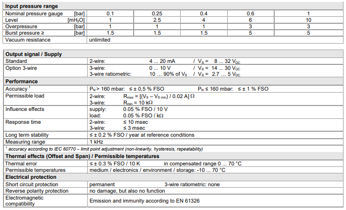
- Hydrostatic Range: 0-1mWC (3.28ftWC) up to 0 – 10mWC (32.8ftWC)
- Output Signals:4-20mA 2 wire or 0-10Vdc 3 wire, 0.5-4.5Vdc ratiometric
- Accuracy: 0.5% full scale
- Electrical Connections: Submersible IP68 sealed gland with PVC coated cable
- Process Connections: G1/4 male with optional nose cone
- Media Compatibility: 304 stainless steel body and process port, 316L stainless steel diaphragm and FKM seal gasket
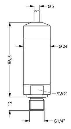
- Dimensions: 24mm diameter
- Weight: 120g approx. plus 25g per metre of cable
Product Description
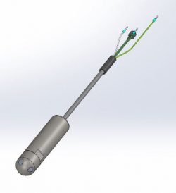
The 18.605 G is designed specifically for use in water and diesel fuel tank applications to measure the level of liquid and determine the quantity of tank contents. This sensor can be connected to tank gauging instrumentation to provide a local indication of tank level or remote telemetry data of diesel fuel or water usage.

This tank level sensor can be installed by lowering into the inside of a tank or by screwing onto the outside of the tank at the bottom via the G1/4 male (1/4 BSP P male) thread. The electrical connection to the tank level sensor is IP68 rated for continuous submersion in diesel fuel or water.
There are five standard level ranges available, starting with a 0 to 0.1 bar (1.5 psi) range for small tanks 1 metre (3.28 feet high), 0.25 bar (3.63 psi), 0.4 bar (5.8 psi), 0.6 bar (8.7 psi), and 1 bar (15 psi) range for 10 metre (33 feet) high tanks.
Depending on connected tank content management instrumentation the sensor can be supplied with a low supply voltage which outputs a 10…90% of supply voltage, a 4-20mA current loop which is convenient for connecting most process instrumentation interfaces, and 0-10Vdc output which is commonly used for the analogue input in building management systems.
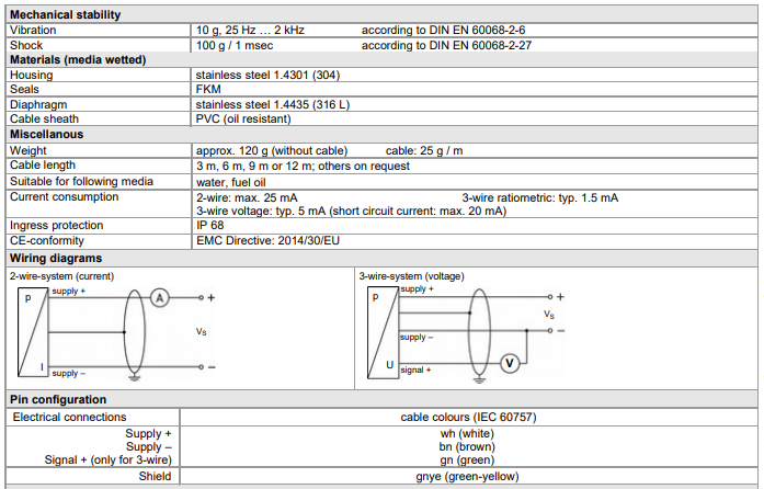
The housing of the sensor is made from stainless steel 304, the diaphragm is stainless steel 316L, FMK seals are used to provide te IP68 watertight seal at the cable exit, and the cable is jacket is made from PVC which is chemical resistant and compatible with most fuel types.
Product Applications
The 18.605 G is a low-cost, submersible OEM pressure transmitter explicitly designed for continuous hydrostatic level measurement in liquid storage environments such as water and fuel oil tanks. This vented gauge sensor provides precise and long-term stable fluid tracking within automated processing networks and high-volume OEM tank configurations.
- Hydrostatic level monitoring inside industrial and commercial water storage systems.
- Inventory tracking and level measurement within fuel oil or diesel tank networks.
- OEM tank integration for automated fluid management systems and processing machinery.
- Continuous telemetry level tracking in shallow ground reservoirs and chemical containment vessels.
- Bulk storage level control for agricultural watering facilities and rural water supply systems.
Product Specification
Product Dimensions
Part Number Configuration
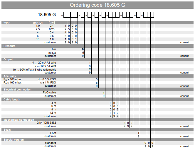
Product Specifying Guide
Step 1: Define the required measurement range and engineering units
Begin by selecting the appropriate full-scale range based on the maximum liquid height in your tank. The sensor can be specified natively in meters of water column (mH2O) ranging from 0…1 mH2O up to 0…10 mH2O, or alternatively calibrated in bar or mbar scales. For low-head tanks, specialized low-pressure ranges down to 100 mbar or 1.2 mH2O are readily selectable to maximize resolution.
Step 2: Select the output signal and supply configuration
Determine the electronic architecture matching your data logging or control system interface. Choose the standard 2-wire 4…20 mA current output loop if you require long-distance signal transmission and strong noise immunity. For voltage-based industrial controllers, opt for the 3-wire 0…10 V configuration, or select the 3-wire ratiometric 10…90% output if operating on low-power, battery-driven telemetry systems.
Step 3: Match accuracy requirements to your pressure range
Review the expected measurement accuracy needed for your control processes. For standard applications with nominal pressures greater than 160 mbar, the sensor delivers an accuracy of <= ±0.5% FSO under limit point adjustment. If your application dictates an ultra-low pressure range of 160 mbar or less, the system automatically shifts to a performance rating of <= ±1% FSO.
Step 4: Establish the cable length
Calculate the exact cable run required to safely exit the tank environment and reach your junction box. Standard pre-configured factory options include 3 m, 6 m, 9 m, or 12 m lengths of oil-resistant PVC shielding.
Part Number Builder
Generate or decode 18.605 G ordering code
Configuration Rules & Restrictions
Pressure Range Dependent Accuracy
The transmitter’s accuracy is strictly tied to the selected nominal pressure range.
- For the low-pressure range of 1.0 mH2O / 0.10 bar (pN <= 160 mbar), the mandatory accuracy code is 8 (1% FSO).
- For all standard pressure ranges from 2.5 mH2O / 0.25 bar up to 10 mH2O / 1 bar (pN > 160 mbar), the mandatory accuracy code is 5 (0.5% FSO).
Note: The Part Number Builder automatically locks and adjusts this setting to guarantee technical validation based on factory limitations.
Cable Length vs. Measurement Depth
When selecting a measurement range for tank level tracking, ensure your chosen cable length is longer than the tank depth or maximum expected liquid head for submersible installations.
Media Wetted Parts
Constructed using durable 1.4301 (304) stainless steel housing, a 1.4435 (316L) stainless steel isolation diaphragm, and an oil-resistant PVC cable sheath.
Ingress Protection
Factory sealed to meet strict IP 68 requirements, accommodating prolonged deployment under fluid loads.
Atmospheric Compensation
The electrical cable contains an internal capillary ventilation tube to automatically balance sensory elements against shifting barometric conditions. Ensure the surface end of the cable terminates in a dry area or weatherproof enclosure to block humidity entry.
Installation & Operation Guide
Step 1: Verify fluid and environmental compatibility
Before deployment, confirm that the medium to be measured is either water, fuel oil, or a closely related compatible fluid. Ensure that the operational temperature profiles of both the medium and the surrounding electronics stay strictly within the allowable bounds of -10 °C to 70 °C. Check that the wetted FKM seals and 316L stainless steel diaphragm are chemically suited for your specific fluid chemistry.
Step 2: Mechanical mounting and sensor placement
Lower the transmitter smoothly into the vessel using the PVC cable body, ensuring it does not strike the tank walls or suffer severe impact. The mechanical connection interface incorporates a G1/4″ male thread matching standard process mounts if fixed-point external placement is preferred. If suspended freely, make sure the probe rests at a fixed height above any heavy sludge layer to maintain unobstructed pressure entry.
Step 3: Route the cable and manage the ventilation path
Ensure the submersible cable is routed cleanly without sharp bends, kinks, or crushing forces that could pinch the internal atmospheric ventilation tube. The open end of the vent tube must terminate in a dry, clean area or a moisture-protected junction box to prevent condensation from entering the tube, as blockages or internal moisture will distort gauge reference readings or permanently damage internal circuitry.
Step 4: Establish electrical wiring connections
With the power supply fully deactivated, connect the individual conductors according to the specified color-coding matrix. Wire the White (WH) lead to the positive supply terminal and the Brown (BN) lead to the negative supply terminal. If a 3-wire voltage variation is utilized, attach the Green (GN) lead to the positive signal terminal. Terminate the Green-Yellow (GNYE) shield wire securely to a functional system ground to prevent electromagnetic interference from compromising reading accuracy.
Product Help
Barometric compensation functionality
How does this sensor correct for variations in local weather and atmospheric pressure?
The level transmitter features an integrated atmospheric ventilation tube built directly inside its submersible PVC cable. This tube runs from the terminated end of the cable down to the rear of the gauge reference sensor element, allowing ambient air pressure to push back against changes in atmospheric weight. This mechanical equalization completely negates the effects of changing weather systems or elevation on tank calculations, guaranteeing that the recorded pressure output is solely derived from the true hydrostatic height of the fluid.
Low power telemetry use cases
Can the transmitter be operated efficiently in remote locations using battery power?
Yes, the transmitter is highly optimized for remote installations when ordered with the 3-wire ratiometric output option. This specific configuration operates on a low supply voltage range of 2.7 to 5 VDC and draws a typical current consumption of only 1.5 mA, minimizing energy draw on remote hardware. This makes it an ideal match for battery-operated wireless telemetry nodes or solar-powered field RTUs where traditional 24 VDC industrial loops are impractical.
Medium temperature limitations
What are the operational temperature limits for the sensor fluid and surroundings?
The transmitter is engineered to operate safely within a temperature window of -10 °C to 70 °C. This range applies uniformly to the liquid medium, the internal sensor electronics, the installation environment, and storage conditions. To prevent measurement drift or reading errors caused by temperature shifts, the device includes active internal compensation across a 0 to 70 °C span, limiting thermal error to a maximum of <= ±0.3% FSO per 10 K.
Reverse polarity wiring safety
Will incorrect electrical wiring during installation destroy the internal components?
No, the transmitter is equipped with integrated reverse polarity protection to shield its sensitive measurement circuitry from deployment errors. If the positive and negative supply lines are inadvertently swapped during commissioning, the device will simply fail to output a signal or function, but it will suffer absolutely no electrical degradation or physical damage. Once the wiring configuration is corrected to match the standard color definitions, the transmitter will resume normal operation.
Protecting from water hammer in discharge pipes
I’ve installed a low-range hydrostatic level sensor (250 mbar / 2.5 mH₂O) directly into the discharge pipe of a diesel fuel tank connected to an engine. The sensor has stopped working, and I suspect damage. Could the “water hammer” effect from the engine shutting down be powerful enough to destroy the sensor, even with a relatively low flow rate?
Yes, it is highly probable that a pressure surge, commonly known as “water hammer” or fluid hammer, caused the sensor failure. This phenomenon occurs when a moving fluid is forced to stop or change direction suddenly, such as when a pump shuts off or a valve closes abruptly. The fluid’s kinetic energy is rapidly converted into pressure energy, creating a high-pressure shockwave that travels back through the piping.
For a low-range sensor, such as a 250 mbar (approximately 3.6 psi) model, this effect can be catastrophic. The 18.605 G series sensor with a 0.25 bar range has a specified overpressure limit of 1 bar (14.5 psi) and a burst pressure of 1.5 bar (21.7 psi). A pressure spike from water hammer can easily exceed these limits, even if the steady-state flow pressure is low. This can permanently deform the sensor’s diaphragm, leading to a complete loss of signal.
To prevent this issue in applications involving pumps, engines, or quick-closing valves, consider these solutions:
- Relocate the Sensor: The ideal location for a hydrostatic level sensor is in a calm area of the tank, away from the turbulence of inlets and outlets, where it only measures the static head of the fluid.
- Install a Pressure Snubber: A pressure snubber or damper can be installed in line with the sensor’s process connection. This device contains a porous element that throttles the flow of the medium, effectively dampening pressure spikes and protecting the delicate sensor diaphragm from damage.
Nose cone usage
When would I need to use the nose cone?
Submersible probes are often fitted with a nose cone to protect the sensitive components at the base of the probe. On this device the sensitive component is already protected by the external thread, so it’s not considered to be an essential accessory in that regard, but it will help prevent sediment from collecting inside the threaded port, and reduce the chance of the thread snagging on any obstructions in the bottom of the tank.
Tank sloshing effects on sensor reading
When using this sensor to measure the level of diesel fuel on a train, does the fuel sloshing while a vehicle is in motion affect the sensor’s reading?
It measures pressure of the liquid above the sensor position, so if the liquid is shifting from side to side this will affect the force acting on the bottom of the tank and what the sensor measures. The instrumentation you are connecting to the sensor may include the ability to average the reading over a rolling time period, which can be used to eliminate effects such as sloshing and provide a stable noiseless reading.
Installing on a tank outlet pipe
Is it a valid installation practice to mount a submersible hydrostatic level transmitter, like the 18.605 G series, into the side of a tank’s outlet pipe instead of lowering it in from the top?
While physically possible, installing a hydrostatic level transmitter directly in an active outlet or discharge pipe is not recommended. These sensors are designed to measure the static pressure head of a column of liquid, which is directly proportional to its level. Placing the sensor in a pipe with moving fluid exposes it to several risks that can lead to inaccurate readings or sensor failure:
- Dynamic Pressure: Fluid flow creates dynamic pressure, which will be added to or subtracted from the static pressure, causing erroneous level readings. For example, the Venturi effect in a flowing pipe can cause a local pressure drop, making the tank level appear lower than it actually is.
- Turbulence: Inlets and outlets are areas of high turbulence. This creates fluctuating pressure readings and can subject the sensor’s diaphragm to mechanical stress and fatigue over time.
- Pressure Spikes: Outlet pipes can be conduits for significant pressure surges caused by pumps starting/stopping or valves operating. A hydrostatic sensor installed in a pipe is directly in the path of these potentially damaging shockwaves.
- Blockages: The sensor’s process connection or diaphragm could become blocked by sediment or debris carried by the flow in the pipe.
For the most accurate and reliable level measurement, the sensor should be fully submerged and suspended in a location where the liquid is calm and non-turbulent, or fitted directly to the side of the tank, or via a short length of dead-ended pipework (dead-leg/blind-end).
Installing vertically or horizontally on tank floor
Does the sensor need to stand vertically or can it be left to rest horizontally on the tank’s floor?
The sensor can measure the level in any orientation, since it is measuring hydrostatic pressure which will be the same in any direction at a particular level in the tank. For very low ranges you may notice a slight change in output depending on orientation, which is due to the g effect on the sensor diaphragm, so if that is the case it is best to calibrate the sensor in the intended orientation it will be installed.
Protecting the sensor port when submerging in tank
The sensor comes with a screw thread and a yellow cover on the sensing end of the device. I see from the instructions that it come with this for screwing into various housings depending upon the application. I was just going to hang the sensor in the tank a few centimetres from the bottom to read the level, do I need to put anything over the threaded opening of the sensor before I put it in the tank?
The yellow cap is a dust cap to prevent any foreign objects entering the pressure port prior to installation, so this should be removed before lowering into the tank.
It will be fine to lower the sensor as you explained, but just to be on the safe side, lower it gently through the surface of the liquid to avoid any pressure shocks, which could damage the diaphragm. Any sudden shocks such as a water hammer or dropping on the floor can damage the sensor because the shock will generate movement in the diaphragm that exceeds it’s pressure rating.
Installing sensor in a vehicle tank
If the tank being measured is on a vehicle, is it adequate to insert it through a top orifice in the tank without having physical access inside to anchor it?
Yes if the sensor is lying on the bottom this can help prevent it moving around, but otherwise you could use a stilling tube of a slightly larger diameter, mounted at the top of the tank, in which you can lower the sensor inside, so that it is protected from movement.
Related Documents
Specification data sheet
Request Product Price
Please select the options you require for the 18.605 G Low Cost Submersible Diesel Fuel and Water Tank Level Sensor in your application and request a quote.