
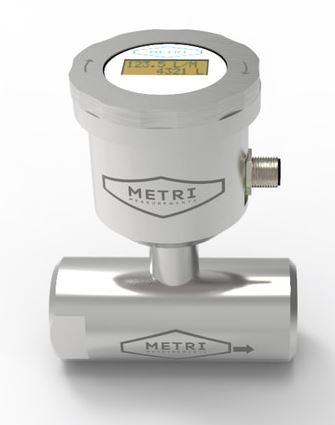
The IC-FMS is an industrial paddle wheel flow meter specifically designed for measuring the flow rate of liquids.
Product Parameters
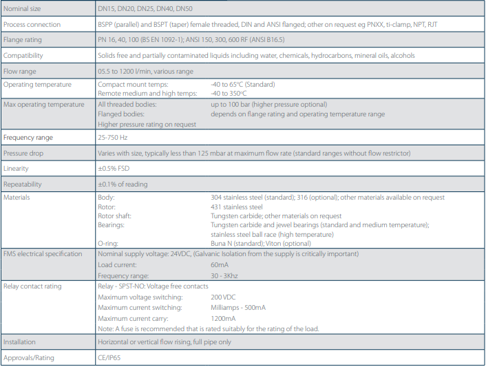
- Flow Ranges: 0…5 L/min up to 1200 L/min
- Process Connections: BSP parallel or tapered female thread, DIN and ANSI flange
- Pipe Size: DN15, DN20, DN25, DN40 or DN50
- Media Compatibility: Solids free and partially contaminated liquids including water, chemicals, hydrocarbons, mineral oils, alcohols
- Operating Temperature Range: Integrated display version -40 to +65 degC, remote display version -40 to +350degC
- Maximum Operating pressure: Threaded versions 100 bar, Flange versions depends on rating
- Frequency Range: 25-750 Hz
- Pressure Drop: Typically less than 125 mbar at max flow rate without flow restrictor
- Linearity: 0.5% FSD
- Repeatability: 0.1% of reading
- Materials: 304 stainless steel body (316 optional), 431 stainless steel rotor, tungsten carbide rotor shaft, tungsten carbide and jewel bearings (stainless steel ball race for hi-temp), Buna N O-rings
- Power Supply: 24Vdc
- Output Signal: 4-20mA and SPST NO voltage free contact alarm relay switch
- Installation: Horizontal or vertical flow rising, full pipe only
- Environmental Protection: IP65, CE marked
Product Description
The IC-FMS display offers users an easy to read and control interface for Analogue 4-20mA (flowrate) with a High or Low relay alarm output which can be configured for flowrate deviation or totalisation (Batch control), all packaged in a rugged stainless-steel body and enclosure.
A variety of connection types, high pressures and temperature ratings make the FMS the ideal partner for a wide variety of general purpose, medical and industrial applications where good repeatability accuracy and a long service life are required.
The display itself is a 36mm x 28mm backlit LCD screen, making it easily visible in dimly lit areas. It has 2 x 10 characters of text providing quick access to flowrate, totalisation and alarm status information.
Flexibility is further enhanced with the option of a remote FMS display away from the flow meter when the meter location is in poor access area’s or in higher temperature applications.
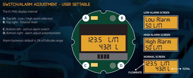
When the alarm is triggered the display flashes until the alarm setpoint has been exceeded. The alarm can be reset once the problem has been identified and resolved.
Principle of Operation
The IC-FMS meter is a velocity-measuring device which is calibrated to indicate volumetric flow of liquids in a pipeline. The IC-IPM meter features a freely supported paddlewheel impeller mounted on a bearing and pin assembly. As the fluid passes through the meter body it causes the paddlewheel to rotate at a speed that is proportional, within a small level of uncertainty, to the stream flow velocity over a 10:1 linear flow range. The rotational speed is measured by a magnetic pick-up housed in the probe assembly.
The paddlewheel is positioned in the top of pipe to avoid solid particle contamination thus preventing possible erosion and/or impact damage which can occur on conventional full bore turbine meters. As a result the IC-FMS flow meter can be used for monitoring partially contaminated liquid flows. In addition the pressure drop across the IC-FMS meter is considerably lower (less than 125 mbar) than an equivalently sized turbine meter as the rotor only obstructs a small fraction of the total flow area.
Specification Details
Each individual meter has a specific standard flow range with a 10:1 turndown ratio and a choice of 3 temperature ratings.
Dimensions


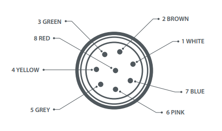
Wiring Connections

Factory Default Settings

Switch / Alarm Adjustment
Part Number Configuration
![]()

Product Help
Accuracy between 1…80 US gpm
Is it possible to achieve 5% accuracy from 80 down to 1 US gal/m?
A 1-80 US gal/m range has a very large turndown ratio between the highest and lowest flow. Typically paddle and turbine meters achieve a 10:1 turndown ratio and this paddle meter is better than this with 20:1 turndown or 8-160 US gpm, but cannot accurately measure your lowest flow between 1 and 8 US gpm.
Locating Flowmeter
The stem of the IC-LPM is marked with an arrow to indicate the direction of flow through the meter. The IC-LPM meter can be installed either horizontally or vertically with flow rising and only with a full pipe.
The preferred mounting position is on top of a horizontal pipe as this ensures that any oversized particles will be flowing below the meter giving added protection to the rotor assembly.
To achieve an optimal electrical signal output from the meter, install well away from current-carrying cables, nearby motors and transformers.
Flow Straightening
Repeatability is important when measuring flow with a paddlewheel meter i.e. the same number of pulse per unit volume is obtained for a particular flow rate. This can only be achieved if the liquid is flowing smoothly and fully “axially” in the pipe (i.e. no “swirl” or flow pulsation present).
For best practice and optimum accuracy, if, for a distance of at least twenty pipe diameters, the upstream pipe work has no fittings such as valves (other than full flow gate or ball valves) or bends (other than large radius tees etc) then allow at least 10 diameters of straight pipe run upstream and 5 diameters downstream of the meter.
Greater straight run lengths may be required when pumps, elbows and valves are installed upstream of the meter; typically allow at least 20 diameters of straight pipe run upstream and 10 diameters downstream of the meter. For larger meters (DN40 and DN50 a flow straightener (Fig A) may be used to reduce the straight run requirements.

Pipe Reduction
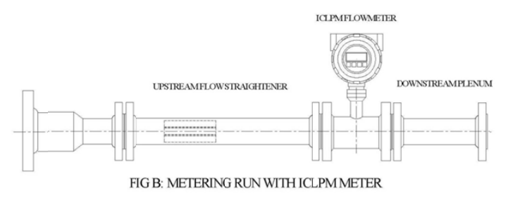
The IC-FSM flow meter is sized to a flow range and not necessarily to match given pipe size. As such, pipe reduction may be required prior to meter installation. Reducers should be tapered cone sections where possible (Fig B) and should be installed with a minimum of 10 diameters of straight run pipe upstream and 5 diameters downstream of the meter.
Tanks & Vessels
Where the meter is installed downstream from a tank/vessel, it is advisable to fit a baffle plate over the hole in the tank to prevent the liquid vortexing through the meter.
Air Entrainment
Air entrainment is to be avoided; where air could be present in the line, an air eliminator should be fitted.
Filtration
A coarse filter should be fitted upstream of the meter for protection against damage by pipe scale, welding splatter and other foreign material etc. A 40 mesh, 400 micron filter is suitable for all meter sizes.
Electrical Installation
Due to the nature of the coil output signal (mV), in particular its susceptibility to noise, twin-core screened twisted cable should be used and correctly earthed. The distance between the meter and signal conditioning electronics should not exceed 20 metres.