
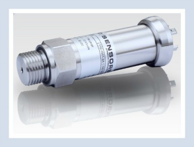
High frequency response pressure sensor with a better than 0.5 millisecond response time and internal digital signal conditioning that samples readings at a rate of 10 kilohertz.
The DMP320 precision pressure transmitter is engineered for dynamic pressure measurement applications requiring exceptional speed and accuracy. Featuring an ultra-fast response time of <= 0.5 msec and a 10 kHz internal sampling rate, the unit effectively captures rapid pressure transients, peaks, and dynamic pressure curves across nominal ranges from -1…0 bar gauge up to 0…600 bar gauge or absolute. High measurement accuracy of <= +-0.10% FSO according to IEC 61298-2 is maintained across demanding thermal environments via active digital error compensation. Built with robust 316L stainless steel wetted components and housed in a compact stainless steel enclosure, the DMP320 delivers reliable long-term stability and high mechanical endurance in demanding plant engineering and industrial process monitoring applications.
Product Parameters
- Pressure Range: 0 to 0.1 up to 600 bar g, abs, compound and negative gauge
- Accuracy: 0.1% FS for ranges 0.25 bar and above, 0.25% for ranges below 0.25 bar
- Output Signal: 3 wire 4-20mA or 0.1-10Vdc
- Response Time: ≤ 0.5 msec with internal sampling rate of 10 kHz
- Electrical Connections: DIN plug, Binder, M12, IP67/68 cable gland, field housing
- Pressure Connectors: 1/4 BSP male DIN3852 or EN837, 1/2 BSP male DIN3852, EN837, DIN3852 open port, 1/4 or 1/2 NPT male
- Media Compatibility: SS316L diaphragm and process connection with FKM or EPDM seals.
- Media Operating Temperature Range: -40 to +125°C
- Ambient Operating Temperature Range: -40…85°C
- Weight: ~200 g
- Dimensions: 26.5 mm diameter
Product Description
The DMP320 is a high precision pressure sensor for use on test systems where the technician is interested in monitoring and recording very dynamic changes in pressure to a high accuracy.
The DMP320 precision pressure transmitter utilizes digital signal processing electronics operating at an internal sampling rate of 10 kHz. This rapid signal acquisition architecture enables active compensation for sensor-specific deviations, including non-linearity, hysteresis, and thermal offset or span errors. Over the compensated temperature range of -20…80°C, the transmitter maintains a tight thermal tolerance band of 0.2% FSO with an average thermal coefficient of +-0.02% FSO / 10 K. Its long-term signal stability rating of 0.1% FSO per year ensures consistent measurement repeatability over prolonged operational cycles.
Engineered for industrial durability, the DMP320 features media-wetted components constructed from high-grade stainless steel 1.4404 (316L) for the pressure port and 1.4435 (316L) for the flush measuring diaphragm. Flexible sealing options include standard FKM or optional EPDM, allowing broad compatibility with various liquid and gaseous process fluids. The transmitter housing is constructed from stainless steel 1.4404 (316L), with an optional stainless steel 1.4301 (304) compact field housing for field environments. Designed to withstand harsh operating environments, the device resists mechanical vibration up to 20 g RMS (10…2000 Hz) and mechanical shocks up to 500 g with a 1 msec half-sine duration.
Designed for straightforward control system integration, the DMP320 offers standard 3-wire signal outputs of 0.1…10 V voltage or 4…20 mA current. Power requirements are met by an auxiliary supply voltage range of 14…30 VDC. Electrical interface configurations include ISO 4400 connectors, Binder series 723 5-pin plugs, M12x1 4-pin metal connectors, compact field housings, and shielded cable outlets with optional ventilation tubes for atmospheric reference tracking. Comprehensive internal electrical safeguards include permanent short-circuit protection and reverse polarity protection.
Product Applications
The DMP320 precision pressure transmitter is designed to deliver superior performance across a diverse array of demanding industrial and research environments. By combining ultra-fast response capabilities with robust, stainless-steel construction, it provides reliable, high-fidelity pressure data essential for sophisticated process monitoring, safety-critical analysis, and precision engineering tasks.
Plant and Machine Engineering
In complex plant and machine engineering environments, the requirement for real-time data is critical. The DMP320’s high-speed response ensures that dynamic pressure changes are captured instantaneously, enabling precise control and optimization of automated manufacturing lines, robotic systems, and assembly machinery where even millisecond delays in pressure feedback could impact throughput or system health.
Energy Sector Applications
For power generation plants and fluid distribution networks, the DMP320 offers the stability and accuracy needed for continuous monitoring. Whether tracking pressure fluctuations in steam turbines, water cooling loops, or natural gas distribution lines, its robust 316L stainless steel design ensures long-term operational integrity and accurate data delivery despite harsh, fluctuating thermal and mechanical conditions.
Hydraulic Circuit Analysis
Hydraulic systems are prone to sudden, damaging pressure spikes, peaks, and ‘water hammer’ effects. The DMP320, with its 10 kHz internal sampling rate, excels at identifying these rapid transient events. By providing a granular view of pressure dynamics, it empowers engineers to diagnose system wear, prevent mechanical fatigue, and optimize the tuning of relief valves and dampeners for safer, more efficient hydraulic circuit operation.
Test Bench and Research Laboratory
In research and development settings, test benches require the highest level of measurement precision and data throughput. The DMP320 provides the high-frequency response and active digital error compensation necessary to validate component performance under stress. Its ability to accurately record rapid pressure cycles and transients makes it an essential tool for material testing, durability trials, and fundamental fluid dynamics research.
Industrial Process Control Loops
Maintaining tight control over process variables is vital for consistency and quality in industrial manufacturing. The DMP320’s high-accuracy signal output (<= 0.1% FSO) and fast update rates allow control systems to react immediately to process disturbances. This minimizes downtime and waste, ensuring that process loops—ranging from chemical processing to food and beverage production—maintain optimal efficiency and strict adherence to quality standards.
OEM System Integration
For original equipment manufacturers (OEMs) building specialized systems, the DMP320 offers a compact, high-precision solution that is easy to integrate into existing designs. Its robust stainless steel construction ensures it can withstand the rigors of various end-user environments, while its versatile electrical output options ensure seamless connectivity with a wide variety of control hardware, simplifying the design-to-production cycle for complex industrial instrumentation.
Product Specifying Guide
Select the nominal pressure range and reference type
Determine the process operational pressure and reference condition required for your measuring application. Gauge pressure options span from -1…0 bar up to 0…600 bar, while absolute pressure options are available from 0.4…0.60 bar up to 0…600 bar. Verify that anticipated process pressure spikes do not exceed the specified overpressure limits (e.g., 40 bar overpressure for a 10 bar nominal range) or burst pressure ratings.
Choose the required output signal format
Select the analogue electrical output format that matches your control interface or data acquisition hardware. Available choices include a 3-wire voltage output of 0.1…10 VDC or a 3-wire current output of 4…20 mA. Both output configurations operate on a supply voltage range of 14…30 VDC.
Determine the process connection thread
Identify the mechanical process connection required for secure mounting into your pipe or manifold. Standard process thread options include G1/4″ DIN 3852, G1/2″ DIN 3852, G1/4″ EN 837, G1/2″ EN 837, 1/4″ NPT, 1/2″ NPT, and a G1/2″ open pressure port version for pressures <= 40 bar.
Select appropriate seal materials
Match the elastomeric sealing ring material to the chemical characteristics and temperature profile of your process fluid. Standard FKM seals provide broad chemical compatibility for process temperatures up to 125°C, while EPDM seals are available as an option for compatible media.
Select the electrical connector and IP protection class
Choose an electrical termination option based on installation conditions and required ingress protection. Available options include an ISO 4400 connector (IP65), Binder series 723 5-pin connector (IP67), M12x1 4-pin metal plug (IP67), compact field housing (IP67), or a cable outlet with an integrated ventilation tube (IP68) for atmospheric reference pressure tracking.
Part Number Builder
Generate or decode DMP 320 ordering code & request quote
Installation & Operation Guide
Mechanical mounting and process seal verification
Prior to mounting, verify that the pressure port thread and mating receptacle are clean and undamaged. Always perform mechanical installation when the system is completely depressurized and de-energized. For DIN 3852 threaded connections, confirm that the elastomeric O-ring is undamaged and properly seated in the designated groove without applying additional sealing material like PTFE tape or hemp. Screw the unit in by hand before tightening with an open-end wrench applied strictly to the wrench flats.
Apply correct tightening torques
Tighten the mechanical process fitting using an appropriate open-end wrench without exceeding permissible torque limits for the specific thread type. Specified tightening torques for metal wrench flats include approx. 5 Nm for G1/4″ DIN 3852, approx. 10 Nm for G1/2″ DIN 3852, approx. 20 Nm for G1/4″ EN 837, approx. 50 Nm for G1/2″ EN 837, approx. 30 Nm for 1/4″ NPT, and approx. 70 Nm for 1/2″ NPT. Never apply wrench torque directly to the transmitter housing to avoid internal component damage or zero-point calibration shifts.
Electrical wiring and pin assignment
Wire the transmitter using a shielded, twisted multicore cable according to the pin assignment table on the product label. Connect the positive supply wire to Supply+, negative supply to Supply-, and signal line to Signal+ for 3-wire current or voltage operation. For cable outlet options with an integrated ventilation tube, ensure the protective PTFE filter element at the cable end remains undamaged and terminates in a dry junction box. Observe minimum cable bending radii during routing (8-fold cable diameter for unvented cable static installation; 10-fold for vented cable).
System commissioning and functional check
Following mechanical and electrical setup, energize the power supply within the specified 14…30 VDC range and gradually pressurize the line. Verify output signals at atmospheric pressure to confirm zero baseline values. Note that the microcontroller-based digital processing unit evaluates measured pressure values continuously with high precision. Perform a visual leak check at process sealing surfaces prior to operational commissioning.
Routine maintenance and cleaning procedures
Perform routine inspections of the housing, process fitting, and electrical cabling for signs of wear, corrosion, or process media accumulation. Clean the external stainless steel housing as required using a soft cloth dampened with a non-aggressive cleaning solution. Never insert pointed mechanical tools or direct compressed air streams against the sensitive measuring diaphragm to prevent permanent diaphragm deformation.
Related Documents
Specification product data sheet
Request Product Price
"*" indicates required fields